DD AF-CA Operating instructions Mode d emploi Manual de instrucciones Manual de instruções
|
|
|
- Nicholas Pinhal
- 5 Há anos
- Visualizações:
Transcrição
1 DD AF-CA Operating instructions Mode d emploi Manual de instrucciones Manual de instruções en fr es pt Printed: Doc-Nr: PUB / / 000 / 01

2 1 This Product is Certified Ce produit est homologué Producto homologado por Este produto está registrado C US Printed: Doc-Nr: PUB / / 000 / 01


3 2 3 4
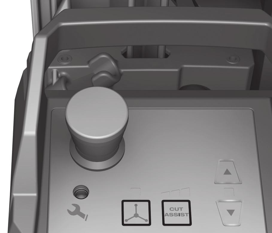
4 ORIGINAL OPERATING INSTRUCTIONS DD AF-CA drilling feed unit It is essential that the operating instructions are read before the appliance is operated for the first time. Always keep these operating instructions together with the appliance. Ensure that the operating instructions are with the appliance when it is given to other persons. Contents Page 1 General information 1 2Description 2 3 Technical data 4 4 Safety instructions 4 5 Setting up 6 6 The core drilling operation 7 7 Disassembly, transport and storage 8 8 Care and maintenance 8 9 Troubleshooting 9 10 Disposal Manufacturer s warranty 11 1 These numbers refer to the illustrations. You can find the illustrations at the beginning of the operating instructions. In these operating instructions, the designation drilling feed unit always refers to the DD AF-CA drilling feed unit. Drilling feed unit on the core drilling system Water regulation valve on the core drilling machine ; Hose connection to the core drilling machine = Water supply connection % Drilling feed unit & Control panel and display ( Drill stand ) Connector for electric power and communication + Core drilling machine Control panel with controls and indicators Emergency stop ; Service LED = Manual mode button and LED % Button and LEDs for Cut Assist mode and power regulation & Positioning buttons with LED en 1 General information 1.1 Safety notices and their meaning DANGER Draws attention to imminent danger that will lead to seriousbodilyinjuryorfatality. WARNING Draws attention to a potentially dangerous situation that could lead to serious personal injury or fatality. CAUTION Draws attention to a potentially dangerous situation that could lead to slight personal injury or damage to the equipment or other property. NOTE Draws attention to an instruction or other useful information. 1.2 Explanation of the pictograms and other information Warning signs General warning Obligation signs Read the operating instructions before use. 1
5 en Symbols Service indicator Return materials for recycling Alternating current Nominal speed under no load Location of identification data on the appliance The type designation and serial number can be found on the type identification plate on the appliance. Make a note of this data in your operating instructions and always refer to it when making an enquiry to your Hilti representative or service department. Type: Generation: 01 Serial no.: Diameter Revolutions per minute Revolutions per minute 2 Description 2.1 Use of the product as directed The drilling feed unit together with the core drilling machines and drill stands recommended by Hilti form an automatic core drilling system suitable for wet core drilling in mineral materials. The drilling feed unit must always be mounted on the drill stand when the unit is in operation. The drill stand must alway be secured using the anchor spindle and a suitable anchor. When the drilling feed unit is used, the drill stand must be securely fastened to the working surface with an anchor. When in operation, the drilling feed unit must be connected to a cooling water supply that meets the minimum specifications given in the technical data. The drilling feed unit has been designed and manufactured in accordance with IP55 and is thus protected against sprayed water. This allows drilling to be carried out without use of a wet-type industrial vacuum cleaner. Observe the safety rules and operating instructions for the accessories used. Observe the national health and safety requirements. The machine or appliance, accessories and cutting tools may present hazards when handled incorrectly by untrained personnel or when used not as directed. NOTE In addition to these operating instructions, the information given in the operating instructions for the other components of the core drilling system must always be observed. DANGER Use only the genuine Hilti accessories or ancillary equipment listed in the operating instructions. Use of accessories or ancillary equipment not listed in the operating instructions may present a risk of personal injury. 2.2 Control panel and display The control panel and display incorporates the emergency stop button as well as buttons and LEDs with controlling and monitoring functions. 2
6 2.3 Operating controls and indicators Emergency stop button Emergency stop Pressing the emergency stop button stops the drilling operation. The core drilling system is still under electric power but operation can be resumed only after the emergency stop button has been released. Releasing the emergency stop button Turn and pull out the emergency stop button and press the Off switch on the core drilling machine. Operation of the core drilling system can then be resumed. Service indicator Service LED blinks red Malfunction that can be remedied, e.g. overheating; see Troubleshooting section. Service LED lights red Disconnect the system from the electric supply and then reconnect; see Troubleshooting section. Mode indicator Manual mode LED on Manual control using the hand wheel is active. en Manual mode LED off Cut Assist is active. Button for manual mode Manual mode is activated by pressing the hand wheel button. In manual mode the water is free to flow. Water from the water supply flows out through the core bit. Manual mode is deactivated by pressing the Cut Assist button. Cut Assist / power control button After switching over from manual mode, Cut Assist is activated with full power available. Pressing the Cut Assist button repeatedly switches the unit to the medium power setting, then to the low power setting and finally back to full power. Cut Assist starts the cooling water flow only when drilling begins and stops the water automatically when the end of the drilling operation is detected. The manual mode button deactivates Cut Assist. Cut Assist power indicator Three LEDs on Full power (preselected after switching on) Two LEDs on Medium power (approx. 85 %) One LED on Low power (approx. 65 %) Carriage positioning buttons These two buttons are active only when in Cut Assist mode and are used exclusively to position the carriage, for example when fitting a core bit. The hand wheel must be removed when using Cut Assist mode. LEDs for carriage positioning LED on Cut Assist is active, the carriage can be positioned using the arrow buttons. LED off Cut Assist is not active, the carriage must be positioned using the hand wheel, or automatic drilling is in progress 2.4 Items supplied 1 DD AF-CA drilling feed unit 1 Securing screw 3
7 1 Operating instructions 1 Cardboard box en NOTE Accessories not supplied with the machine are available from your Hilti Center or can be ordered online at 3 Technical data Right of technical changes reserved. Rated voltage 240 V 480 V Rated frequency Hz Hz Rated current input 0.4 A 0.25 A Output voltage [DC] 5 V Output current 50 ma Speed of rotation 0 75/min Highest permissible water supply pressure Max. 6 bar (Max psi) Minimum water flow rate per minute Min. 0.5 l (Min gal) (water temperature: Max. +30 C (Max. +86 F)) Dimensions (L W H) 361 mm (14.21") 193 mm (7.6") 133 mm (5.24") Weight, ready for use 4.5 kg (9.92 lb) Protection class I (grounded) Protected against dust and water IP55 4 Safety instructions 4.1 General Power Tool Safety Warnings a) WARNING Read all safety warnings and instructions. Failure to follow the warnings and instructions may result in electric shock, fire and/or serious injury. Save all warnings and instructions for future reference. The term power tool in the warnings refers to your mains-operated (corded) power tool or batteryoperated (cordless) power tool Workareasafety a) Keep work area clean and well lit. Cluttered or dark areas invite accidents. b) Do not operate power tools in explosive atmospheres, such as in the presence of flammable liquids, gases or dust. Power tools create sparks which may ignite the dust or fumes. c) Keep children and bystanders away while operating a power tool. Distractions can cause you to lose control Electrical safety a) Power tool plugs must match the outlet. Never modify the plug in any way. Do not use any adapter plugs with earthed (grounded) power tools. Unmodified plugs and matching outlets will reduce risk of electric shock. b) Avoid body contact with earthed or grounded surfaces such as pipes, radiators, ranges and refrigerators. There is an increased risk of electric shock if your body is earthed or grounded. c) Do not expose power tools to rain or wet conditions. Water entering a power tool will increase the risk of electric shock. d) Do not abuse the cord. Never use the cord for carrying, pulling or unplugging the power tool. Keep cord away from heat, oil, sharp edges or moving parts. Damaged or entangled cords increase the risk of electric shock. e) When operating a power tool outdoors, use an extension cord suitable for outdoor use. Use of a cord suitable for outdoor use reduces the risk of electric shock. f) If operating a power tool in a damp location is unavoidable, use a residual current device (RCD) protected supply. Use of an RCD reduces the risk of electric shock Personal safety a) Stay alert, watch what you are doing and use common sense when operating a power tool. Do 4
8 not use a power tool while you are tired or under the influence of drugs, alcohol or medication. A moment of inattention while operating power tools may result in serious personal injury. b) Use personal protective equipment. Always wear eye protection. Protective equipment such as dust mask, non-skid safety shoes, hard hat, or hearing protection used for appropriate conditions will reduce personal injuries. c) Prevent unintentional starting. Ensure the switch is in the off position before connecting to power source and/or battery pack, picking up or carrying the tool. Carrying power tools with your finger on the switch or energising power tools that have the switch on invites accidents. d) Remove any adjusting key or wrench before turning the power tool on. Awrenchorakeyleftattached to a rotating part of the power tool may result in personal injury. e) Do not overreach. Keep proper footing and balance at all times. This enables better control of the power tool in unexpected situations. f) Dress properly. Do not wear loose clothing or jewellery. Keep your hair, clothing and gloves away from moving parts. Loose clothes, jewellery or long hair can be caught in moving parts. g) If devices are provided for the connection of dust extraction and collection facilities, ensure these are connected and properly used. Use of dust collection can reduce dust-related hazards Power tool use and care a) Do not force the power tool. Use the correct power tool for your application. The correct power tool will do the job better and safer at the rate for which it was designed. b) Do not use the power tool if the switch does not turn it on and off. Any power tool that cannot be controlled with the switch is dangerous and must be repaired. c) Disconnect the plug from the power source and/or the battery pack from the power tool before making any adjustments, changing accessories, or storing power tools. Such preventive safety measures reduce the risk of starting the power tool accidentally. d) Store idle power tools out of the reach of children and do not allow persons unfamiliar with the power tool or these instructions to operate the power tool. Power tools are dangerous in the hands of untrained users. e) Maintain power tools. Check for misalignment or binding of moving parts, breakage of parts and any other condition that may affect the power tool s operation. If damaged, have the power tool repaired before use. Many accidents are caused by poorly maintained power tools. f) Keep cutting tools sharp and clean. Properly maintained cutting tools with sharp cutting edges are less likely to bind and are easier to control. g) Use the power tool, accessories and tool bits etc. in accordance with these instructions, taking into account the working conditions and the work to be performed. Use of the power tool for operations different from those intended could result in a hazardous situation Service a) Have your power tool serviced by a qualified repair person using only identical replacement parts. This will ensure that the safety of the power tool is maintained. 4.2 Proper organization of the workplace a) Approval must be obtained from the site engineer or architect prior to beginning drilling work. Drilling work on buildings and other structures may influence the statics of the structure, especially when steel reinforcing bars or load-bearing components are cut through. b) When drilling through walls, cover the area behind the wall, as material or the core may fall out on the other side of the wall. When drilling in a downward direction, cordon off or cover the area below as drilled material or the core may drop out and fall down. c) Wear respiratory protection if the work causes dust. d) It is recommended that rubber gloves and nonskid shoes are worn when working outdoors. e) Keep the supply cord, extension cord, suction hose and vacuum hose away from rotating parts. f) Do not work from a ladder General safety measures a) Tampering with or modification of the drilling feed unit, drill stand and accessories is strictly prohibited. b) Keep the grips dry, clean and free from oil and grease. c) Never leave the appliance unattended. d) Store appliances in a secure place when not in use.when not in use, appliances must be stored in a dry, high place or locked away out of reach of children. e) Children must be instructed not to play with the appliance. f) This appliance is not intended for use by persons (including children) with reduced physical, sensory or mental capabilities, or lack of experience and knowledge, unless they have been given supervision or instruction concerning use of the appliance by a person responsible for their safety. g) Check the appliance and its accessories for any damage. Guards, safety devices and any slightly damaged parts must be checked carefully to ensure that they function faultlessly and as intended. Check that moving parts function correctly without sticking and that no parts are damaged. All parts must be fitted correctly and fulfill all conditions necessary for correct operation of the appliance. Damaged guards, safety devices and other parts must be repaired or replaced properly at an en 5
9 en authorized service center unless otherwise indicated in the operating instructions. h) Avoid skin contact with drilling slurry. i) Wear a protective mask during work that generates dust, e.g. dry drilling. Connect a dust removal system. Drilling into materials hazardous to the health (e.g. asbestos) is not permissible. j) Dust from material such as paint containing lead, some wood species, minerals and metal may be harmful. Contact with or inhalation of the dust may cause allergic reactions and/or respiratory diseases to the operator or bystanders. Certain kinds of dust are classified as carcinogenic such as oak and beech dust especially in conjunction with additives for wood conditioning (chromate, wood preservative). Material containing asbestos must only be treated by specialists. Where the use of a dust extraction device is possible it shall be used. To achieve a high level of dust collection, use a suitable vacuum cleaner of the type recommended by Hilti for wood dust and/or mineral dust together with this tool. Ensure that the workplace is well ventilated. The use of a dust mask of filter class P2 is recommended. Follow national requirements for the materials you want to work with Mechanical a) Follow the instructions concerning care and maintenance. b) Follow the instructions concerning lubrication andchangingcorebits. c) Check that the core bits used are compatible with the chuck system and that they are secured in the chuck correctly. d) Check that the drilling feed unit is correctly and securely mounted on the drill stand. e) Do not touch rotating parts. f) Check that all the clamping screws are correctly tightened. g) Make sure that the cover with built-in end stop is always fitted to the drill stand. The safetyrelevant end-stop function becomes inoperative if this component is not fitted Electrical a) Check the appliance s supply cord at regular intervals and have it replaced at a Hilti service center if damage is found. Check extension cords at regular intervals and replace them if damage is found. b) Do not touch the supply cord or extension cord if they are damaged while working. Disconnect the supply cord plug from the power outlet. c) In case of an interruption in the electric supply: Switch off the machine and/or appliance and unplug the supply cord. d) Avoid using extension cords with multiple power outlets and the simultaneous use of several appliances connected to one extension cord. e) Never operate the appliance when it is dirty or wet. Dust (especially dust from conductive materials) or dampness adhering to the surface of the appliance may, under unfavorable conditions, lead to electric shock. Dirty or dusty appliances should thus be checked at a Hilti service center at regular intervals, especially if used frequently for working on conductive materials. f) Before beginning work, check the working area (e.g. using a metal detector) to ensure that no concealed electric cables or gas and water pipes are present. External metal parts of the appliance may become live, for example, when an electric cable is damaged accidentally. This presents a serious risk of electric shock. 5Settingup 5.1 Mounting the drilling feed unit on the carriage on the drill stand 3 CAUTION While setting up the drilling feed unit, the core drilling machine must be disconnected from the electric supply. CAUTION The supply voltage must comply with the specification given on the type identification plate. The drilling feed unit may be connected only to the core drilling machines recommended by Hilti for operation in this way. DANGER Make sure that the drilling feed unit is correctly mounted and secured on the drill stand. NOTE Checkthatthecarriageisofthetypesuitableforusewith an automatic feed unit: At the position of the mounting screwtheremustbeaholethatallowsthemounting screw to be pushed through. Mount the drilling feed unit as follows: 1. Use the hand wheel to position the carriage so that the drilling feed unit can be mounted conveniently. 2. Lock the carriage. 3. Bring the drilling feed unit into position on the carriage and hold it there. 4. If the drilling feed unit does not fit evenly against the drill stand, unlock the carriage and turn the hand wheel slightly until the drilling feed unit makes full contact with the carriage. 5. Insert the fastening screw through the carriage and into the drilling feed unit. 6. Screw the fastening screw into the drilling feed unit and tighten it by hand. 7. Remove the hand wheel. 6
10 8. Connect the water hose that runs to the core drilling machine. 9. Connect the water supply to the drilling feed unit. 10. Remove the protective caps from the connector and the connecting cable. 11. CAUTION Connect a 110 volt drilling feed unit only to a 110 volt core drilling machine. Connect the connecting cable for the drilling feed unit to the connector on the core drilling machine. 12. Fit the protective caps into each other in order to keep them clean. 5.2 Providing water cooling NOTE Both the drilling feed unit and the core drilling machine are water cooled devices. Before operating the equipment, always check that a water hose is correctly connected to the water input connector for the drilling feed unit cooling circuit. This also applies when carrying out dry drilling applications. Check that the minimum water flow rate meets at least the requirements given in the technical data. en 6 The core drilling operation NOTE Switching other power tools or appliances on and off may cause undervoltage and / or overvoltage peaks, resulting in damage to the power tool or appliance. Never operate other power tools or appliances from the generator or transformer at the same time. DANGER Failure to keep clear of the danger area may result in a risk of crushing or cutting injury. The drilling feed unit is always in Cut Assist mode immediately after switching on and starts drilling automatically as soon as the switch on the core drilling machine is operated. When the drilling operation is started, the core bit is moved toward the working surface. There is a risk of injury in the vicinity of the core drilling machine, the core bit and at the point where the hole is to be drilled. Before switching on the core drilling machine, check that no persons are within the danger area. WARNING There is a risk of crushing or cutting injury when the core drilling system contacts the working surface with the core bit. Keep everything clear of the area between the core bit and the working surface. CAUTION The emergency stop button does not function if the drilling feed unit is not connected to the core drilling machine. Do not carry out manual core drilling when the drilling feed unit is fitted but not connected. Remove the drilling feed unit when it is not connected to the core drilling machine or, alternatively, connect it to the core drilling machine. 6.1 Working principle In Cut Assist mode, the core drilling operation begins with the core bit being moved (drilling feed movement) towardsthesurfaceinwhichtheholeistobedrilled. The core bit does not rotate while this is taking place. As soon as the core bit contacts the surface it is retracted a short distance. The core bit then begins to rotate slowly (starting speed). The system switches on the water supply and drills at low speed until adequate hole-starting depth is reached. Once the required starting depth has been reached the system continues drilling at the optimum speed and with optimum power. The Iron Boost function is activated automatically when the core bit contacts a reinforcing bar, thereby adjusting the power output for optimum performance while cutting through the reinforcement. Thin, weak reinforcing bars may not be detected by the drilling feed unit, in which case the Iron Boost function will not be activated. This has only a very slight effect on drilling performance. When drilling a blind hole (not all the way through), the drilling feed unit stops the advance movement as soon as the carriage contacts the depth gauge. NOTE When through holes are drilled without using a depth gauge, the core bit feed movement continues until the core bit projects approx. 3 cm beyond the through hole exit. At the end of the drilling operation the core bit should be retracted so that just the tip of the core bit remains in the hole, and the water flow then switched off. 6.2 Drilling using Cut Assist mode WARNING The rotating hand wheel presents a risk of injury! Remove the hand wheel from the carriage before you begin drilling using CutAssist. NOTE If you press the Iron Boost button on the core drilling machine while using Cut Assist mode, automatic power regulation when drilling through reinforcing bars will be deactivated. As a result, until the end of the drilling operation, you will then have to regulate the drilling power manually when drilling through reinforcing bars. To drill a hole automatically using Cut Assist, proceed as follows: 7
11 en 1. Start the water flow by pressing the manual mode button and then wait until water flows out at the core bit. 2. Activate the Cut Assist mode. 3. If necessary, adjust drilling power by pressing the Cut Assist button. NOTE For more information about controlling drilling power, please refer to the section describing the controls and indicators. 4. Start the drilling operation as described in the operating instructions for the core drilling machine. 5. End the drilling operation as described in the operating instructions for the core drilling machine. 6.3 Drilling in manual mode 1. Press the manual mode button on the drilling feed unit. This starts the water flowing, i.e. water flows through the cooling circuit for the core drilling machine and flows out through core bit. 2. Carry out the manual drilling operation as described in the operating instructions for the core drilling machine. 6.4 Breaks between work and storage at low temperatures DANGER At temperatures below 4 C (39 F) the water in the cooling circuit must be blown out with compressed air when drilling is interrupted for more than on hour or before the equipment is stowed away. In order to drain the water circuit the core drilling machine must be connected to the electric supply and to the drilling feed unit. 1. Disconnect the water supply from the drilling feed unit. 2. Open the water regulation valve on the core drilling machine. 3. Set the 3-way valve on the core drilling machine to Wet drilling. 4. Activate manual mode on the drilling feed unit in order to allow the water to flow. 5. Use compressed air (max. 3 bar) to blow the water out of the water circuit. 7 Disassembly, transport and storage 7.1 Dismantling the drilling feed unit 4 The drilling feed unit can be dismantled independently of the core drilling machine. Dismantle the drilling feed unit as follows: 1. Separate the protective caps for the connecting cable and connector, which are fitted into each other. 2. Unplug the connecting cable for the drilling feed unit from the connector on the core drilling machine. 3. Fit the protective caps to the connecting cable and to the connector. 4. Disconnect the water hose that runs to the core drilling machine. 5. Lock the carriage. 6. Secure the drilling feed unit to prevent it falling and, at the same time, release the fastening screw. 7. Remove the drilling feed unit and lay it down in a safe place. 7.2 Transport and storage Open the water flow regulator before putting the core drilling machine into storage. CAUTION When temperatures drop below freezing point, check to ensure that no water remains in the core drilling system. DANGER Transport the drilling feed unit, core drilling machine, drill stand and core bit as separate units. Use the wheel assembly (accessory) as an aid when transporting the equipment. 8 Care and maintenance CAUTION Unplug the core drilling machine s supply cord from the power outlet. 8.1 Care of the appliance CAUTION Keep the appliance, especially its grip surfaces, clean and free from oil and grease. Do not use cleaning agents which contain silicone. 8

12 Clean the outside of the appliance at regular intervals with a slightly damp cleaning cloth. Do not use spray systems, steam pressure cleaning systems or high-pressure water jet systems when cleaning. This may negatively affect the electrical safety of the appliance. 8.2 Care of core bits and metal parts Remove any dirt adhering to the surface of core bits, the chuck and drive spindle and protect their surfaces from corrosion by rubbing them with an oily cloth from time to time. 8.3 Maintenance WARNING Repairs to the electrical section of the appliance may be carried out only by trained electrical specialists. Check all external parts of the drilling feed unit for damage at regular intervals and check that all controls operate faultlessly. Do not operate the drilling feed unit if parts are damaged or when the controls do not function faultlessly. Repairs should be carried out by Hilti Service. 8.4 Checking the appliance after care and maintenance After carrying out care and maintenance, check that all protective and safety devices are fitted and that they function faultlessly. en 9 Troubleshooting Fault Possible cause Remedy The cable cannot be connected to the core drilling machine. The drilling feed unit can t be fitted. The LEDs on the drilling feed unit don t light when the buttonontheprcdforthecore drilling machine is pressed. The hand wheel cannot be rotated. The plug connector is dirty. The plug connector or cable is defective. The bushing for the fastening screw is clogged or obstructed. The thread on the fastening screw or in the hole is defective. The cable is damaged. The connector is faulty. The plug connector is dirty. Faulty connecting cable. The carriage is locked. The carriage is obstructed. Unplug the core drilling machine from the power outlet. Clean the plug connector. Without using force, try again to plug in the connector. Contact Hilti Service. Clean the threaded bushing Contact Hilti Service. Contact Hilti Service. Unplug the core drilling machine from the power outlet. Check the connector between the drilling feed unit and the core drilling machine. If the cable or connector are faulty, return the unit to Hilti Service. Unplug the core drilling machine from the power outlet. Check the plug connection between the drilling feed unit and the core drilling machine. If the cable or connector are faulty, return the unit to Hilti Service. Unplug the core drilling machine from the power outlet. Check the plug connection between the drilling feed unit and the core drilling machine. If the cable or connector are faulty, return the unit to Hilti Service. Unlock the carriage. Make sure that the carriage is free to move. 9
13 en Fault Possible cause Remedy The hand wheel cannot be rotated. The gearing section of the drilling Contact Hilti Service. feed unit is defective. The carriage gearing is defective. Contact Hilti Service. The service LED blinks. Fault that can be remedied (e.g. emergency stop button pressed in, overheating, communication error). 1.) Release the emergency stop button. 2.) If overheating occurs, allow the machine to cool down. 3.) Check the connecting cable. 4.) Acknowledge and cancel the error status by pressing the Off switch on the core drilling machine. The service LED lights constantly. The water flow rate is too low. Water drips from the casing of the drilling feed unit. The drilling feed unit motor runs but the carriage doesn t move. Cut Assist mode cannot be activated. The drilling operation slows or stops. Critical error or fault. The core drilling machine water valve is blocked or defective. The drilling feed unit solenoid valve is blocked or defective. The water circuit is defective. The solenoid valve is defective. The drilling feed unit is fitted incorrectly. The gearing section of the drilling feed unit is defective. The carriage gearing is defective. The plug connector for the core drilling machine is faulty. The motor is defective. The gearing is defective. The electronics are defective. The switch is defective. The emergency stop button is pressed in. The core bit is defective (segments polished or damaged). Unplug the core drilling machine from the power outlet, wait 5 seconds, and then plug it in again. Contact Hilti Service if the service indicator LED continues to light. Check that the water supply is installed correctly. Check whether the valve is blocked or defective. Contact Hilti Service. Check that the water supply is installed correctly. Check whether the valve is blocked or defective. Contact Hilti Service. First disconnect the core drilling machine from the electric supply. Disconnect the system from the water supply. Contact Hilti Service. First disconnect the core drilling machine from the electric supply. Disconnect the system from the water supply. Contact Hilti Service. Check the mechanical connection between the drilling feed unit and the carriage. Contact Hilti Service. Contact Hilti Service. Check the plug connection. Contact Hilti Service. Contact Hilti Service. Contact Hilti Service. Contact Hilti Service. Release the emergency stop button. Sharpen or replace the core bit. 10
14 Fault Possible cause Remedy The drilling operation slows or stops. The plug connection is faulty or the cable is defective. The core bit is stuck. Faulty or inadequate cooling. Stop before reaching the target depth due to transition into softer material such as hollow brick, soil or natural stone. Check the connection between the drilling feed unit and the core drilling machine. If the cable is faulty, return the unit to Hilti Service. Disconnect the core drilling machine fromtheelectricsupply. Release the core bit. Check the water supply and cooling circuit. Restart the drilling operation. en 10 Disposal Most of the materials from which Hilti tools, machines or appliances are manufactured can be recycled. The materials must be correctly separated before they can be recycled. In many countries, Hilti has already made arrangements for taking back old tools, machines and appliances for recycling. Ask Hilti customer service or your Hilti representative for further information. Recommended pretreatment before disposal of drilling slurry NOTE Disposal of drilling slurry directly into rivers, lakes or the sewerage system without suitable pretreatment presents environmental problems. Ask the local public authorities for information about current regulations. 1. Collect the drilling slurry (e.g. using a wet-type industrial vacuum cleaner). 2. Allow the drilling slurry to settle and dispose of the solid material at a constructionwastedisposalsite(addition of a flocculent may accelerate the settling process). 3. The remaining water (alkaline, ph value > 7) must be neutralized by the addition of an acidic neutralizing agent or diluted with a large volume of water before it is allowed to flow into the sewerage system. 11 Manufacturer s warranty Please contact your local Hilti representative if you have questions about the warranty conditions. 11
15 NOTICE ORIGINALE DD AF-CA Unité d'avance de perçage fr Avantdemettrel'appareilenmarche,lireimpérativement son mode d'emploi et bien respecter les consignes. Le présent mode d'emploi doit toujours accompagner l'appareil. Ne pas prêter ou céder l'appareil à un autre utilisateur sans lui fournir le mode d'emploi. Sommaire Page 1 Consignes générales 12 2Description 13 3 Caractéristiques techniques 15 4 Consignes de sécurité 15 5 Installation 18 6 Réalisation d'un carottage 19 7 Démontage, transport et entreposage 20 8 Nettoyage et entretien 20 9 Guide de dépannage Recyclage Garantie constructeur des appareils 23 1 Les numéros renvoient aux illustrations. Les illustrations se trouvent au début de la notice d'utilisation. Dans le texte du présent mode d emploi, le terme «unité d'avance de perçage» désigne toujours l'unité d'avance de perçage DD AF-CA. Unitéd'avancedeperçagesurlesystèmedecarottage Dispositif de régulation du débit d'eau sur le dispositif de carottage ; Raccord de flexible vers le dispositif de carottage = Raccordement à l'arrivée d'eau % Unité d'avance de perçage & Panneau de commande et d'affichage ( Colonnedeforage ) Fiche de raccordement pour l'alimentation électrique et communication + Dispositif de carottage Panneau de commande avec organes de commande et éléments d'affichage Arrêt d'urgence ; LED Service = ToucheetLEDModemanuel % Touche et LED pour le mode Cut Assist et la régulation de puissance & Touches de positionnement avec LED 1 Consignes générales 1.1 Termes signalant un danger et leur signification DANGER Pour un danger imminent qui peut entraîner de graves blessures corporelles ou la mort. AVERTISSEMENT Pour attirer l'attention sur une situation pouvant présenter des dangers susceptibles d'entraîner des blessures corporelles graves ou la mort. ATTENTION Pour attirer l'attention sur une situation pouvant présenter des dangers susceptibles d'entraîner des blessures corporelles légères ou des dégâts matériels. REMARQUE Pour des conseils d'utilisation et autres informations utiles. 1.2 Explication des pictogrammes et autres symboles d'avertissement Symboles d'avertissement Avertissement danger général Symboles d'obligation Lire le mode d'emploi avant d'utiliser l'appareil 12
16 Symboles Indicateur de maintenance Recyclage des matériaux Courant alternatif Vitesse nominale à vide Identification de l'appareil La désignation du modèle et le numéro de série se trouvent sur la plaque signalétique de l'appareil. Inscrire cesrenseignementsdanslemoded'emploiettoujours s'y référer pour communiquer avec notre représentant ou agence Hilti. Type : fr Génération : 01 N de série : Diamètre Tours par minute Tours par minute 2 Description 2.1 Utilisation conforme à l'usage prévu Avec un dispositif de carottage et une colonne de forage recommandés par Hilti, l'unité d'avance de perçage constitue un système de carottage automatique conçu pour le carottage humide dans des matériaux minéraux. En cours de fonctionnement, l'unité d'avance de perçage doit toujours être montéesurlacolonnedeforage. La colonne de forage doit toujours être sécurisée au moyen de chevilles et brides d'ancrage appropriées. Lors de l'utilisation de l'unité d'avance de perçage, la colonne de forage doit être suffisamment ancrée dans le sol de l'infrastructure. Pour fonctionner, l'unité d'avance de perçage doit être raccordée à une alimentation en eau de refroidissement, satisfaisant aux exigences minimales des spécifications techniques. L'unité d'avance de perçage est conçue et fabriquée selon la classe de protection IP55, et est par conséquent protégée contre les projections d'eau. Le forage est ainsi possible sans utilisation d'un aspirateur d'eau industriel. Respecter également les instructions de sécurité et d'utilisation de l'accessoire utilisé. Observer les exigences en matière de sécurité nationales en vigueur. L'appareil, les accessoires et les outils peuvent entraîner des dangers s'ils sont utilisés par un personnel non qualifié, de manière non appropriée ou non conforme à l'usage prévu. REMARQUE Outre le présent mode d emploi, il convient également de toujours prendre en compte les notices d'utilisation des autres composants du système de carottage. DANGER N'utiliser que des accessoires ou adaptateurs d'origine qui figurent dans le présent mode d'emploi. L'utilisation d'autres accessoires ou éléments que ceux recommandés dans le mode d'emploi risque de provoquer des blessures. 2.2 Panneau de commande et d'affichage Le panneau de commande et d'affichage contient le bouton-poussoir Arrêt d'urgence ainsi que des touches et LED de commande et de surveillance. 13
17 fr 2.3 Organes de commande et éléments d'affichage Bouton-poussoir Arrêt d'urgence Déclenchement d'un arrêt d'urgence Indicateur de maintenance Annulation d'un arrêt d'urgence LED Service clignote en rouge LED Service allumée en rouge L'actionnement du bouton-poussoir Arrêt d'urgence arrête l'opération de forage. Le système de carottage reste sous tension, mais peut seulement être à nouveau utilisé une fois le boutonpoussoir Arrêt d'urgence relâché Tourner et retirer le bouton-poussoir Arrêt d'urgence et appuyer sur le bouton d'arrêt du dispositif de carottage. Le système de carottage est ensuite à nouveau opérationnel Défaillance remédiable, p. ex. température excessive ; voir chapitre Guide de dépannage Débrancher le système du réseau et le rebrancher ; voir chapitre Guide de dépannage Affichage de mode LED Mode manuel allumée Commande manuelle par volant à main activée LED Mode manuel éteinte Cut Assist activé Touche du mode Manuel Pour activer le mode Manuel, appuyer sur la touche Volant à main. L'arrivée d'eau est ouverte en mode Manuel. L'eau amenée sort de la couronne de forage. Pour désactiver le mode Manuel, appuyer sur la touche Cut Assist. Touche Cut Assist/régulation de puissance Après avoir commuté en mode Manuel, Cut Assist est activé à pleine puissance. Réappuyer sur la touche Cut Assist pour sélectionner la puissance moyenne, puis réduite et à nouveau la pleine puissance. Cut Assistouvrel'arrivéed'eauàl'amorceduperçageetlacoupedèsladétection de la fin du perçage. La touche du mode Manuel désactive Cut Assist. Affichage de la puissance pour Cut Assist Trois LED allumées Pleine puissance (réglage par défaut après la mise en marche) Deux LED allumées Puissance moyenne (environ 85 %) Une LED allumée Puissance réduite (environ 65 %) Touches pour positionnement du boîtier de guidage Les deux touches sont uniquement disponibles en mode Cut Assist et servent exclusivement à positionner le boîtier de guidage, par exemple pour le montage de la couronne de forage. En mode Cut Assist, le volant àmaindoitêtreenlevé. LED de positionnement du boîtier de guidage LED allumée LED éteinte Cut Assist est activé, le boîtier de guidage peut être positionné au moyen des touches fléchées Cut Assist est désactivé, le boîtier de guidage doit être positionné à l'aide du volant à main, ou opération de perçage automatique en cours 14
18 2.4 Équipement livré 1 Unité d'avance de perçage DD AF-CA 1 Vis de fixation 1 Mode d'emploi 1 Emballage en carton REMARQUE Les accessoires qui ne sont pas contenus dans l'équipement fourni peuvent être obtenus auprès du S.A.V. Hilti ou en ligne sous Sécurité relative au système électrique a) La fiche de secteur de l outil électroportatif doit être appropriée à la prise de courant. Ne modifiez en aucun cas la fiche. N'utilisez pas de fiches d adaptateur avec des outils électroportatifs avec miseàlaterre. Les fiches non modifiées et les prises de courant appropriées réduisent le risque de choc électrique. b) Éviter le contact physique avec des surfaces mises à la terre tels que tuyaux, radiateurs, cuifr 3 Caractéristiques techniques Sous réserve de modifications techniques! Tension nominale 240 V 480 V Fréquence nominale Hz Hz Courant nominal 0,4 A 0,25 A Tension de sortie [c.c.] Courant de sortie Vitesse de rotation Pression d'alimentation en eau maximale admissible Débit d'eau minimal à la minute Dimensions(L l H) Poids de service Classe de protection Protection contre la poussière et l'eau 5 V 50 ma 0 75/min Max. 6 bar (Max. 87,02 psi) Min. 0,5 l (Min. 0,13 gal) (Température de l'eau : Max. +30 C (Max. +86 F)) 361mm(14,21") 193mm(7,6") 133mm(5,24") 4,5 kg (9,92 lb) I (mis à la terre) IP55 4 Consignes de sécurité 4.1 Indications générales de sécurité pour les appareils électriques a) AVERTISSEMENT Lire et comprendre toutes les consignes de sécurité et instructions. Le non-respect des consignes de sécurité et instructions indiquées ci-après peut entraîner un choc électrique, un incendie et / ou de graves blessures sur les personnes. Les consignes de sécurité et instructions doivent être intégralement conservées pour les utilisations futures. La notion d «outil électroportatif» mentionnée dans les consignes de sécurité se rapporte à des outils électriques raccordés au secteur (avec câble de raccordement) et à des outils électriques à batterie (sans câble de raccordement) Sécurité sur le lieu de travail a) Maintenez l endroit de travail propre et bien éclairé. Un lieu de travail en désordre ou mal éclairé augmente le risque d accidents. b) N'utilisez pas l'outil électroportatif dans un environnement présentant des risques d explosion et où se trouvent des liquides, des gaz ou poussières inflammables. Les outils électroportatifs génèrent des étincelles risquant d enflammer les poussières ou les vapeurs. c) Tenez les enfants et autres personnes éloignés durant l utilisation de l outil électroportatif. En cas d inattention vous risquez de perdre le contrôle de l appareil. 15
19 fr sinières et réfrigérateurs. Il y a un risque élevé de choc électrique au cas où votre corps serait relié à la terre. c) N'exposez pas les outils électroportatifs à la pluie ou à l humidité. La pénétration d eau dans un outil électroportatif augmente le risque d un choc électrique. d) N'utilisez pas le câble à d autres fins que celles prévues, n'utilisez pas le câble pour porter l'outil électroportatif ou pour l accrocher ou encore pourledébrancherdelaprisedecourant.maintenez le câble éloigné des sources de chaleur, des parties grasses, des bords tranchants ou des parties de l appareil en rotation. Un câble endommagéoutorsadéaugmentelerisqued unchoc électrique. e) Au cas où vous utiliseriez l outil électroportatif à l extérieur, utilisez uniquement une rallonge homologuée pour les applications extérieures. L utilisation d une rallonge électrique homologuée pour les applications extérieures réduit le risque d un choc électrique. f) Si l'utilisation de l'outil électroportatif dans un environnement humide ne peut pas être évitée, un interrupteur de protection contre les courants de court-circuit doit être utilisé. L'utilisation d'un tel interrupteur de protection réduit le risque d'une décharge électrique Sécurité des personnes a) Restez vigilant, surveillez ce que vous faites. Faites preuve de bon sens en utilisant l outil électroportatif. N'utilisez pas l'outil électroportatif lorsque vous êtes fatigué ou après avoir consommé de l alcool, des drogues ou avoir pris des médicaments. Un moment d inattention lors de l utilisation de l'outil électroportatif peut entraîner de graves blessures sur les personnes. b) Portez des équipements de protection. Portez toujours des lunettes de protection. Le fait de porter des équipements de protection personnels tels que masque antipoussière, chaussures de sécurité antidérapantes, casque de protection ou protection acoustique suivant le travail à effectuer, réduit le risque de blessures. c) Éviter une mise en service par mégarde. S'assurer que l'outil électroportatif est arrêté avant de le brancher à la source de courant et/ou au bloc-accu, de le prendre ou de le porter. Le fait de porter l'outil électroportatif avec le doigt sur l interrupteur ou de brancher l appareil sur la source de courant lorsque l interrupteur est en position de fonctionnement, peut entraîner des accidents. d) Enlevez tout outil de réglage ou toute clé avant de mettre l'outil électroportatif en fonctionnement. Une clé ou un outil se trouvant sur une partie en rotation peut causer des blessures. e) Adoptez une bonne posture. Veillez à garder toujours une position stable et équilibrée. Ceci vous permet de mieux contrôler l'outil électroportatif dans des situations inattendues. f) Portez des vêtements appropriés. Ne portez pas de vêtements amples ni de bijoux. Maintenez cheveux, vêtements et gants éloignés des parties de l appareil en rotation. Des vêtements amples, des bijoux ou des cheveux longs peuvent être happés par des pièces en mouvement. g) Si des dispositifs servant à aspirer ou à recueillir les poussières doivent être utilisés, vérifiez que ceux-ci sont effectivement raccordés et qu ils sont correctement utilisés. L'utilisation d'un dispositif d'aspiration peut réduire les risques dus aux poussières Utilisation et maniement de l'outil électroportatif a) Ne surchargez pas l'appareil. Utilisez l outil électroportatif approprié au travail à effectuer. Avec l'outil électroportatif approprié, vous travaillerez mieux et avec plus de sécurité à la vitesse pour laquelle il est prévu. b) N'utilisez pas un outil électroportatif dont l interrupteur est défectueux. Un outil électroportatif qui ne peut plus être mis en ou hors fonctionnement est dangereux et doit être réparé. c) Retirez la fiche de la prise de courant et/ou le bloc-accu avant d'effectuer des réglages sur l'appareil, de changer les accessoires, ou de ranger l'appareil. Cette mesure de précaution empêche une mise en fonctionnement par mégarde de l'outil électroportatif. d) Gardez les outils électroportatifs non utilisés hors de portée des enfants. Ne permettez pas l utilisation de l appareil à des personnes qui ne se sont pas familiarisées avec celui-ci ou qui n ont pas lu ces instructions. Lesoutilsélectroportatifssont dangereux lorsqu ils sont utilisés par des personnes non initiées. e) Prendre soin des outils électroportatifs. Vérifier que les parties en mouvement fonctionnent correctement et qu elles ne sont pas coincées, et contrôler si des parties sont cassées ou endommagées de sorte que le bon fonctionnement de l outil électroportatif s en trouve entravé. Faire réparer les parties endommagées avant d utiliser l'appareil. De nombreux accidents sont dus à des outils électroportatifs mal entretenus. f) Maintenez les outils de coupe aiguisés et propres. Des outils soigneusement entretenus avec des bords tranchants bien aiguisés se coincent moins souvent et peuvent être guidés plus facilement. g) L'outil électroportatif, les accessoires, les outils à monter, etc. doivent être utilisés conformément à ces instructions. Tenez compte également des conditions de travail et du travail à effectuer. L utilisation des outils électroportatifs à d autres fins que celles prévues peut entraîner des situations dangereuses Service a) Ne faire réparer l'outil électroportatif que par un personnel qualifié et seulement avec des pièces 16
20 de rechange d origine. Ceci permet d assurer la sécurité de l'outil électroportatif. 4.2 Agencement ergonomique du lieu de travail a) Faire confirmer les travaux de forage par la direction des travaux. Les travaux de forage dans des bâtiments et autres structures sont susceptibles de modifier la statique de la construction, en particulier lors d'interventions sur des armatures métalliques ou desélémentsporteurs. b) En cas de perçages à travers un mur, sécuriser la zone située derrière le mur, étant donné que du matériau ou la carotte de perçage risquent de tomber derrière. En cas de perçages vers le bas, veiller à protéger un périmètre de sécurité au sol, étant donné que du matériau ou la carotte de forage risquent de tomber. c) Porter un masque respiratoire pour les travaux dégageant de la poussière. d) Lors d'interventions à l'extérieur, le port de gants en caoutchouc et de chaussures à semelle antidérapante est recommandé. e) Tenir le câble d'alimentation réseau, le câble de rallonge et le tuyau d'aspiration à l'écart des pièces en rotation. f) Ne pas travailler à partir d'une échelle Consignes de sécurité générales a) Il est interdit de manipuler ou de modifier l'unité d'avance de perçage, la colonne de forage ainsi que les accessoires. b) Les poignées doivent toujours être sèches, propres et exemptes de toutes traces de graisse ou d'huile. c) Ne jamais laisser l'appareil sans surveillance. d) Conserver les appareils non utilisés en toute sécurité.tous les appareils non utilisés doivent être rangés dans un endroit sec, en hauteur ou fermé à clé, hors de portée des enfants. e) Avertir les enfants et veiller à ce qu'ils ne jouent pas avec l'appareil. f) L'appareil n'est pas conçu pour être utilisé par des personnes (y compris des enfants) ayant des déficiences motrices, sensorielles ou mentales, ou manquant d'expérience et/ou ayant des connaissances insuffisantes, à moins qu'elles ne soient surveillées par une personne responsable de leur sécurité ou qu'elles aient reçu des instructions de cette personne leur indiquant comment utiliser correctement cet appareil. g) Vérifier que l'appareil et les accessoires ne présentent pas de dommages éventuels. Avant toute autre utilisation, les dispositifs de sécurité et les pièces légèrement endommagées doivent être soigneusement contrôlés pour garantir un excellent fonctionnement, conforme aux spécifications. Vérifier que toutes les pièces mobiles fonctionnent parfaitement et ne coincent pas, et que les pièces ne sont pas abîmées. Toutes les pièces doivent être montées correctement et remplir toutes les conditions propres à garantir le parfait fonctionnement de l'appareil. Les dispositifs de sécurité et les pièces endommagés doivent être réparés ou remplacés de manière professionnelle par un atelier spécialisé agréé, sauf indication contraire dans le mode d'emploi. h) Éviter que la peau n'entre en contact avec les boues de forage. i) Lors de travaux générant de la poussière, par ex. lors du forage à sec, porter un masque respiratoire. Raccorder un dispositif d'aspiration des poussières. Il est interdit de forer des matériaux nocifs pour la santé (par ex. amiante). j) Lespoussièresdematériauxtellesquedespoussières de peinture au plomb, de certains types de bois, minéraux et métaux, peuvent être nocives pour la santé. Le contact ou l'aspiration des poussières peut provoquer des réactions allergiques et/ou des maladies respiratoires de l'utilisateur ou de toute personne se trouvant à proximité. Certaines poussières, telles que des poussières de chêne ou de hêtre, sont considérées comme cancérigènes, en particulier lorsqu'elles sont combinées à des additifs destinés au traitement du bois (chromate, produit de protection du bois). Les matériaux contenant de l'amiante doivent seulement être manipulés par un personnel spécialisé. Un dispositif d'aspiration doit être utilisé dans la mesure du possible. Pour une aspiration optimale de la poussière, utiliser de préférence l'aspirateur mobile approprié pour bois et/ou poussières minérales recommandé par Hilti, qui est spécialement étudié pour cet outil électroportatif. Veiller à ce que la place de travail soit bien ventilée. Il est recommandé de porter un masque antipoussière de la classe de filtre P2. Respecter les prescriptions locales en vigueur qui s'appliquent aux matériaux travaillés Mécaniques a) Bien respecter les instructions relatives au nettoyage et à l'entretien de l'appareil. b) Observer les instructions concernant la lubrification et le changement d'outil. c) Vérifier que les outils sont bien munis du système d'emmanchement adapté à l'appareil et qu'ils sont toujours correctement verrouillés dans le porte-outil. d) Vérifier que l'unité d'avance de perçage est correctement fixée dans la colonne de forage. e) Ne toucher aucune des pièces en rotation. f) Vérifier que toutes les vis de blocage sont bien serrées. g) Veiller à ce que le couvercle avec butée d'extrémité intégrée sur la colonne de forage soit toujours monté, sans quoi la fonction butée d'extrémité de sécurité n'est pas assurée Électriques a) Contrôler régulièrement les câbles de raccordement de l'appareil et les faire remplacer par le S.A.V. Hilti s'ils sont endommagés. Contrôler réfr 17
Platinum Electric Griddle. Children should be supervised to ensure that they do not play with the appliance.
 Platinum Children should be supervised to ensure that they do not play with the appliance. 1 2 ELECTRIC GRIDDLE 1. Receptacle for power probe 2. Side handle 3. Non-stick heating plate 4. Power cable with
Installation Instructions
 page 1 of 7 Description This 3-piece shield is designed to further reduce side-lobe radiation levels of high-performance, parabolic antennas. The instructions given in this bulletin apply to a shield for
LIGHT PANEL CONTENTS Light Panel Power supply Fixtures (brackets, screws)
") Page 1 of 8 LIGHT PANEL 20367 CONTENTS Light Panel Power supply Fixtures (brackets, screws) ABOUT THIS PRODUCT The Light Panel may be used on a table top as a free-standing object, or mounted either horizontally
Page 1 of 8 LIGHT PANEL 20367 CONTENTS Light Panel Power supply Fixtures (brackets, screws) ABOUT THIS PRODUCT The Light Panel may be used on a table top as a free-standing object, or mounted either horizontally
Manual de instruções para Caixa Coletora Johnson Pump
 Manual de instruções para Caixa Coletora Johnson Pump Em caso dúvidas na instalação após a leitura do manual, favor entrar em contato com nosso departamento técnico através do telefone: (11) 3477-5655
Nome empresa: Criado por: Telefone:
 Texto da proposta Data: 22-1-216 SCALA2 3-45 A Grundfos SCALA2 is a fully integrated, self-priming, compact waterworks for pressure boosting in domestic applications. SCALA2 incorporates integrated speed
DD AF-CA Operating instructions Mode d emploi Manual de instrucciones Manual de instruções
 DD AF-CA Operating instructions Mode d emploi Manual de instrucciones Manual de instruções fr es pt Printed: 15.10.2015 Doc-Nr: PUB / 5236039 / 000 / 01 1 This Product is Certified Ce produit est homologué
GEAR PUMPS RECOMMENDATIONS BEFORE START-UP
 GEAR PUMPS RECOMMENDATIONS BEFORE START-UP CTI Gear pumps recommendations before start-up 0811-0 Attention: The application of ABER gear pumps must follow all the instructions hereby mentioned in order
Miniature Solenoid Valve Type 200
 2/2-Way, Direct-acting, G1/8 - M5 Advantages/Benefits Normally closed Body materials: brass, stainless steel Short response time Compact design Design/Function Applications is a direct-acting plungertype
Operator Manual Thermoplan AG, Subject to change REV-0
 1 Overview Control panel Foamer head Cup platform Liner pouch 8 Overview Heating basin Milk foam tube Level controller Milk container Cover Hood 9 Putting into operation Plug the appliance into a suitable
PRODUCT FAMILY DATASHEET SubstiTUBE PURE
 SubstiTUBE PURE Economic LED tubes for electromagnetic control gears AREAS OF APPLICATION Corridors, stairways, parking garages Cooling and storage rooms Warehouses Domestic applications General illumination
Thank you for using Shepherd 240 Biometric Fingerprint Lock. Please read this Installation Manual carefully before attempting
 Preface Thank you for using Shepherd 240 Biometric Fingerprint Lock Please read this Installation Manual carefully before attempting to install your new lock. This manual covers installation procedures
Torre Purificadora de Ar MCP-
 Filtro de cartuchos compacto com pulsos de limpeza A torre de purificação de ar MCP-16 RC é um filtro de cartuchos compacto para limpeza e reciclagem do ar interior. A unidade filtrante compacta é fornecida
SONDA DE ÁGUA QUENTE SANITÁRIA
 SONDA DE ÁGUA QUENTE SANITÁRIA PT Avisos preliminares Estas instruções são parte integrante do manual do aparelho no qual o KIT é instalado. Consulte este manual para as ADVERTÊNCIAS GERAIS e REGRAS FUNDAMENTAIS
2/4 BD8201FM. Lot No. REV. A
 1/4 2/4 BD8201FM Lot No. 3/4 Ω Function Description 4/4 Appendix Notes No technical content pages of this document may be reproduced in any form or transmitted by any means without prior permission of
1. Product Name. 2. Product Code. 3. Colour. 4. Brief Description. 5. Contents. 6. Snoezelen Stimulations. Switch Adapted Fibre Optic Lamp
 1. Product Name Switch Adapted Fibre Optic Lamp 2. Product Code 20709 3. Colour Clear base; white fibres 4. Brief Description Activate your switch to activate the light through the fibres and in the base.
Desumidificador de ar
 MANUAL DO USUÁRIO USER MANUAL Desumidificador de ar Baby Care Português 4// Manual do Usuário Parabéns! Você acaba de adquirir mais um produto com a qualidade Multilaser! O Desumidificador de Ar Multilaser
Manual de instruções para Sifões VETUS e Johnson Pump
 Manual de instruções para Sifões VETUS e Johnson Pump Em caso dúvidas na instalação após a leitura do manual, favor entrar em contato com nosso departamento técnico através do telefone: (11) 3477-5655
SONDA CASCATA. Avisos preliminares CONTEÚDO FERRAMENTAS RECOMENDADAS NEXPOLAR
 SONDA CASCATA PT Avisos preliminares Estas instruções são parte integrante do manual do aparelho no qual o KIT é instalado. Consulte este manual para as ADVERTÊNCIAS GERAIS e REGRAS FUNDAMENTAIS DE SEGURANÇA.
WS3231 WS3231U. Atornillador eléctrico PT P04 Screw gun EN P09
 WS3231 WS3231U Atornillador eléctrico PT P04 Screw gun EN P09 Fig.A Fig.B Fig.C Fig.D LISTA DE COMPONENTES 1. Mandril 2. Controle de ajuste de torque 3. Seletor de sentido de rotação (direita ou esquerda)
1. Product Name. 2. Product Code. 3. Colour. 4. Brief Description. 5. Contents. Peek A Boo Bear. Light brown bear the colour of the blanket may vary
 1. Product Name Peek A Boo Bear 2. Product Code 20837 3. Colour Light brown bear the colour of the blanket may vary 4. Brief Description Activate your switch to make this adorable bear play peek a boo.
T 350 T-Racer Surface Cleaner
 T 350 T-Racer Surface Cleaner Deutsch 4 English 6 Français 8 Italiano 10 Nederlands 12 Español 14 Português 16 Dansk 18 Norsk 20 Svenska 22 Suomi 24 Ελληνικά 26 Türkçe 28 Русский 30 Magyar 33 Čeština 35
1. Product Name. 2. Product Code. 3. Colour. 4. Brief Description. 5. Contents. Switch Adapted Clip On Fan. Colours may vary
 1. Product Name Switch Adapted Clip On Fan 2. Product Code 20489 3. Colour Colours may vary 4. Brief Description Connects to your switch for switch activation. 5. Contents Fan with cable with 3.5mm jack
VGM. VGM information. ALIANÇA VGM WEB PORTAL USER GUIDE June 2016
 Overview The Aliança VGM Web portal is an application that enables you to submit VGM information directly to Aliança via our e-portal Web page. You can choose to enter VGM information directly, or to download
Dallas RMD 169 Texas DJ
 Radio / MD Dallas RMD 69 Texas DJ Installation instructions Notice de montage Instrucciones de instalación Instruções de montagem G Safety precautions Installation and connection regulations In the event
Leica Sprinter 50 / 150 / 150M / 250M Push the Button
 Leica Sprinter 50 / 150 / 150M / 250M Push the Button Leica Sprinter 50 / 150 Construction Levels Product Offering Sprinter 50 (Standard / US) Art. No. 762628 / 764686 Sprinter 50, 2.0 mm, electronic level
Operação de Instalações Marítimas
 ENIDH, Abril 2011 Sumário 1 Steering Gear 2 Bow Thrust 3 Propeller Servo 1 Steering Gear 2 Bow Thrust 3 Propeller Servo Steering Gear System Comprises two identical hydraulic systems. Each system includes:
1. Product Name. 2. Product Code. 3. Colour. 4. Brief Description. 5. Contents. 6. Snoezelen Stimulations. Fibre Optic UFO
 1. Product Name Fibre Optic UFO 2. Product Code 16692 3. Colour Transparent base*; white fibres * Base may be silver-coloured, subject to availability 4. Brief Description Captivating, fine fibre optics.
User Manual. Linksys PAP2 Broadband Phone Service. Linhagratuita grupo csdata
 User Manual Linksys PAP2 Broadband Phone Service Linhagratuita grupo csdata www.linhagratuita.com.br Please follow the step-by-step guide below to set up your Linksys PAP2 for use with Linhagratuita Broadband
1. Product Name 2. Product Code 3. Colour 4. Brief Description 5. Contents 6. Snoezelen Stimulations
 1. Product Name Wheel Rotator 2. Product Code 13170, 16570, 20685 3. Colour Black 4. Brief Description A wheel rotator is needed to rotate the effect wheel in the ROMPA Projector. 5. Contents 1 x Wheel
ÍNDICE PORTUGUÊS INDEX ENGLISH
 ÍNDICE PORTUGUÊS 1. Características do Produto...2 2. Aplicação...2 3. Manual de Operação...2 4. Diferença entre os adaptadores AC e DC...3 5. Utilizando o Adaptador DC 12V...3 6. Utilizando o Adaptador
Stick Up Cam Battery
 Stick Up Cam Battery 1. Charge and insert the battery. Charge the provided battery. First, fully charge the battery by plugging it into a USB port using the provided orange cable. The battery is fully
WI FI INTERACTIVE MAT SWITCH SET 19939
 Page 1 of 6 WI FI INTERACTIVE MAT SWITCH SET 19939 CONTENTS 1 x Control Box with 9V battery 9 x carpet switches: 1 x pink vinyl 1 x purple carpet 1 x blue non-slip mat 1 x green Soft & Silky 1 x light
WS3100 WS3100U. Furadeira de impacto 500W PT P06 500W Impact drill EN P11
 WS3100 WS3100U Furadeira de impacto 500W PT P06 500W Impact drill EN P11 1 2 3 8 7 6 4 5 _ + Fig.A Fig.B Fig.C Fig.D Fig.E Fig.F Lista DE componentes 1. Limitador de profundidade 2. Comutador de função
WS3145 WS3145U. Furadeira de impacto 750W PT P06 750W impact drill EN P11
 WS3145 WS3145U Furadeira de impacto 750W PT P06 750W impact drill EN P11 1 2 3 7 4 5 8 6 Fig.A Fig.B Fig.C _ + Fig.D Fig.E Fig.F Lista de componentes 1. Mandril com chave 2. Limitador da espessura 3. Seletor
1. Product Name. 2. Product Code. 3. Colour. 4. Brief Description. 5. Contents. Hip Hop Jumping Cushion. Colours may vary
 1. Product Name Hip Hop Jumping Cushion 2. Product Code 19229 3. Colour Colours may vary 4. Brief Description Provides hours of healthy fun for children. Has a strong padding and has no frame or edges.
Quick user guide. (réf )
") Quick user guide (réf. 34889) Download the app «mobile eye door +» How to SETUP, for the first time, your Chacon IP VDP Connect the cables with the same color to each other, of both units. Connect the
Quick user guide (réf. 34889) Download the app «mobile eye door +» How to SETUP, for the first time, your Chacon IP VDP Connect the cables with the same color to each other, of both units. Connect the
1. Product Name. 2. Product Code. 3. Colour. 4. Brief Description. 5. Contents. 6. Snoezelen Stimulations. 1 x Hanging Bracket.
 1. Product Name Hanging Bracket 2. Product Code 13672 3. Colour Blue 4. Brief Description Purpose made bracket designed for fixing to timber or metal. The shape of the hook gives a secure fixing but allows
VGM. VGM information. ALIANÇA VGM WEB PORTAL USER GUIDE September 2016
 Overview The Aliança VGM Web portal is an application that enables you to submit VGM information directly to Aliança via our e-portal Web page. You can choose to enter VGM information directly, or to download
SAVANNAH GEORGIA USA
 EK200LS CASED CFA SAVANNAH GEORGIA USA THE COMPANY CZM has over 40 years of foundation equipment manufacturing experience with a wide range of models for multiple applications: drilled shafts, CFA, driven
de lo normal. A continuación, póngase en contacto con un electricista cualificado. Los datos antes mencionados podrán modificarse sin previo aviso par
 de lo normal. A continuación, póngase en contacto con un electricista cualificado. Los datos antes mencionados podrán modificarse sin previo aviso para introducir mejoras en el producto. 12 Limpar
Manual do usuário. User s Manual. Music Bass subwoofer 4 em 1 SP101 Music Bass subwoofer 4 in 1 SP101. Music bass subwoofer 4 em 1
 Manual do usuário User s Manual Music Bass 2.1 - subwoofer 4 em 1 SP101 Music Bass 2.1 - subwoofer 4 in 1 SP101 1 sp101_manual.indd 1 10/11/2010 12:40:11 ÍNDICE INSTRUÇÕES DE SEGURANÇA.....................................................................................................
Manual de Instruções para Buzinas a Ar Marinco
 Manual de Instruções para Buzinas a Ar Marinco Em caso dúvidas na instalação após a leitura do manual, favor entrar em contato com nosso departamento técnico através do telefone ou email: (11) 3477-5655
Manual de instruções para Alarme de Alagamento Johnson Pump
 Manual de instruções para Alarme de Alagamento Johnson Pump Em caso dúvidas na instalação após a leitura do manual, favor entrar em contato com nosso departamento técnico através do telefone: (11) 3477-5655
Hailo ( )
") Hailo 1-2-3 500 (9459-551) Aluminium-Gerüst Aufbauanleitung Aluminium scaffolding Assembly instructions Echafaudage aluminium Instructions de montage Andamio de aluminio Instrucciones de montaje Ponteggio
Hailo 1-2-3 500 (9459-551) Aluminium-Gerüst Aufbauanleitung Aluminium scaffolding Assembly instructions Echafaudage aluminium Instructions de montage Andamio de aluminio Instrucciones de montaje Ponteggio
1 WC System. Instrução Técnica Instrucción Técnica Technical Instruction
 WC System . WC SYSTEM Technical characteristics: Electro-pneumatic system The toilet mechanism works with pneumatic energy supplied by the chassis's pneumatic system. The water timer is done by a relay,
WX128 WX128.1 WX128.2 WX128.3 WX128.4 WX128.9
 PT EN P07 P15 WX128 WX128.1 WX128.2 WX128.3 WX128.4 WX128.9 1 2 3 4 5 9 8 6 7 A1 A2 A3 B1 1 2 B2 C1 2 1 C2 C3 D F E 1. MANDRIL 2. COMUTADOR DE TORQUE 3. COMUTADOR DE VELOCIDADE MECÂNICO (1 E 2) 4. ROTAÇÃO
Automotive Retrofit Procedure
 Automotive Retrofit Procedure Replacing R-12 with R-134a Tom Birch Refrigerant Choice R-134a is the only Significant New Alternative Policy (SNAP), single-molecule refrigerant. R-134a is used by all original
Pesquisa Qualitativa do Início ao Fim (Métodos de Pesquisa) (Portuguese Edition)
 (Portuguese Edition)") Pesquisa Qualitativa do Início ao Fim (Métodos de Pesquisa) (Portuguese Edition) Robert K. Yin Click here if your download doesn"t start automatically Pesquisa Qualitativa do Início ao Fim (Métodos de
Pesquisa Qualitativa do Início ao Fim (Métodos de Pesquisa) (Portuguese Edition) Robert K. Yin Click here if your download doesn"t start automatically Pesquisa Qualitativa do Início ao Fim (Métodos de
Série de acessórios e válvulas de bola de PVC Máxima garantia na circulação da água da piscina
 Série de acessórios e válvulas de bola de PVC Máxima garantia na circulação da água da piscina Range of PVC accessories and ball valves Ensure perfect water circulation in your pool Série de acessórios
WS4151 WS4151U. Lixadeira oscilante PT P06 Palm sander EN P11
 WS4151 WS4151U Lixadeira oscilante PT P06 Palm sander EN P11 1 2 9 3 4 8 7 6 5 10 7 Fig.A Fig.B Fig.C 11 1 Fig.D Fig.E Fig.F Fig.G Lista de componentes 1. Interruptor Liga/Desliga 2. Empunhadura com punho
Importante. 13. Não ultrapassar a capacidade máxima do recipiente. 14. Não utilizar o Espremedor de Citrinos por períodos muito longos.
 Importante 1.Leia todas as instruções cuidadosamente antes de usar o espremedor de citrinos Orima. 2. Este aparelho pode ser usado por crianças de 8 anos ou mais e pessoas com reduzidas capacidades físicas,
MARQUE: BABYLISS REFERENCE: E751E CODIC:
 MARQUE: BABYLISS REFERENCE: E751E CODIC: 4209494 NOTICE Made in China Made in China 1 3 4 2 6 5 Fig. 1 Fig. 2 Fig. 3 Fig. 4 Fig. 5 Fig. 6 BABYLISS 99 avenue Aristide Briand - 92120 Montrouge - France www.babyliss.com
Copyright ROMPA Ltd SNORING PIG 20134
 SNORING PIG 20134 CONTENTS 1 x Snoring Pig with cable attached Please note: Snoring Pig requires, but does not include 3 x AA batteries. BEFORE USE 1. Lay the pig down so that his head is facing to the
SUMÁRIO PORTUGUÊS INDEX ENGLISH
 SUMÁRIO PORTUGUÊS Componentes do produto...2 Sugestões de uso: pescoço, ombro, perna, braço, cintura...2 Os defeitos mais comuns e como resolvê-los...3 Utilização:...3 INDEX ENGLISH Product Components...6
CRIMP OD & PRODUCT GUIDE HOSE ID
 .50 0.58 0.660.049 05022C50** E05C E05E 0.60 0.676.049 05022CS** 05C 05E 0.62 0.692.049 (.688 ) CF50C CF50E 0.64 0.707.049 05024C50** 0.66 0.723.049 05024CS** 0.68 0.738.049 (.750 ) 0.70 0.754.049 05026C50**
Power Amp.
 Power Amp. www.nortonaudio.com Vista Frontal 1 - Potenciómetro de Volume do Canal Esq. 2 - Potenciómetro de Volume do Canal Dir. 3 - LED de Clip. 4 - LED de Protecção. 5 - Interruptor On/Off Vista Traseira
VC Series Round Vinyl Caps
 1 VC Series Round Vinyl Caps (Round Vinyl Caps) Series VC Caps are extremely flexible and durable protective closures which are ideal for use as thread protectors, dust and moisture seals, pipe and stud
ATLAS DE ACUPUNTURA VETERINáRIA. CãES E GATOS (EM PORTUGUESE DO BRASIL) BY CHOO HYUNG KIM
 BY CHOO HYUNG KIM") Read Online and Download Ebook ATLAS DE ACUPUNTURA VETERINáRIA. CãES E GATOS (EM PORTUGUESE DO BRASIL) BY CHOO HYUNG KIM DOWNLOAD EBOOK : ATLAS DE ACUPUNTURA VETERINáRIA. CãES E GATOS Click link bellow
Read Online and Download Ebook ATLAS DE ACUPUNTURA VETERINáRIA. CãES E GATOS (EM PORTUGUESE DO BRASIL) BY CHOO HYUNG KIM DOWNLOAD EBOOK : ATLAS DE ACUPUNTURA VETERINáRIA. CãES E GATOS Click link bellow
WS3160K WS3160KU. Martelete SDS-plus PT P05 Rotary Hammer EN P10
 WS3160K WS3160KU Martelete SDS-plus PT P05 Rotary Hammer EN P10 1 2 3 4 5 6 7 Fig.A Fig.B Fig.C Fig.D Fig.E Fig.F Fig.G1 Fig.G2 LISTA DE COMPONENTES 1. Mandril com encaixe SDS-Plus 2. Parafuso de travamento
MSW. MSW Catalog Number Sequence. Standard Features MSW 25 B- 3
 Introducing the New WEG Series. The was developed according to IEC 60947-3 & UL508. The compact, reliable design of the allows the operator to safely disconnect power and isolate the circuit within the
WS3174 WS3174U. Furadeira de impacto 650W PT P04 650W Impact drill EN P09
 WS3174 WS3174U Furadeira de impacto 650W PT P04 650W Impact drill EN P09 1 2 3 6 4 5 7 Fig.A Fig.B Fig.C Fig.D Fig.E Fig.F LISTA DE COMPONENTES 1. Mandril com chave 2. Limitador da espessura 3. Seletor
Conversação Para Viagem - Inglês (Michaelis Tour) (Portuguese Edition)
 (Portuguese Edition)") Conversação Para Viagem - Inglês (Michaelis Tour) (Portuguese Edition) Antonio Carlos Vilela Click here if your download doesn"t start automatically Conversação Para Viagem - Inglês (Michaelis Tour) (Portuguese
Conversação Para Viagem - Inglês (Michaelis Tour) (Portuguese Edition) Antonio Carlos Vilela Click here if your download doesn"t start automatically Conversação Para Viagem - Inglês (Michaelis Tour) (Portuguese
Biscuit - potes (Coleção Artesanato) (Portuguese Edition)
 (Portuguese Edition)") Biscuit - potes (Coleção Artesanato) (Portuguese Edition) Regina Panzoldo Click here if your download doesn"t start automatically Biscuit - potes (Coleção Artesanato) (Portuguese Edition) Regina Panzoldo
Biscuit - potes (Coleção Artesanato) (Portuguese Edition) Regina Panzoldo Click here if your download doesn"t start automatically Biscuit - potes (Coleção Artesanato) (Portuguese Edition) Regina Panzoldo
Instructions AK-PC 551
 Instructions AK-PC 551 Identification 1,5 m: 080G0075 3,0 m: 080G0076 080G0281 = 230 V a.c. 20 VA 080G0283 = 24 V a.c. / d.c. 17 VA 080G0321 = 230 V a.c. 20 VA 080G0326 = 24 V a.c. / d.c. 17 VA MMIGRS2:
WS3140K WS3140KU. Martelete SDS-plus 650W PT P06 650W Rotary hammer EN P11
 WS3140K WS3140KU Martelete SDS-plus 650W PT P06 650W Rotary hammer EN P11 11 1 2 3 5 4 9 6 7 10 8 Fig.A Fig.B Fig.C Fig.D Fig.E Fig.F Fig.G Fig.H Fig.I Lista de componentes 1. Acoplamento de trava do mandril
WEIGHTED BLANKET 17689
 WEIGHTED BLANKET 17689 CONTENTS 1 x Weighted Blanket Instructions and maintenance check list USE For indoor use only. Use under supervision. CARE & MAINTENANCE Using the maintenance check list supplied,
*Raccordement correct nécessaire pour une de commutation de passage zéro
 310 317 0 LUNA LUNA 109 109 0 100, 109 0 00 110 0 100, 110 0 00 F Notice de montage et d utilisation Interrupteur crépusculaire Test 000 LUNA 109 I:-35 II : 35-00 III : 00-1000 min max IV:1-5klx V: 5-50klx
DEG 500-D/ DEG 600-D/-P
 DEG 500-D/ DEG 600-D/-P Operating instructions Mode d emploi Manual de instrucciones Manual de instruções en es pt Printed: 09.12.2013 Doc-Nr: PUB / 5138164 / 000 / 01 1 This Product is Certified Ce produit
Farmacologia na Pratica de Enfermagem (Em Portuguese do Brasil)
") Farmacologia na Pratica de Enfermagem (Em Portuguese do Brasil) Click here if your download doesn"t start automatically Farmacologia na Pratica de Enfermagem (Em Portuguese do Brasil) Farmacologia na Pratica
Farmacologia na Pratica de Enfermagem (Em Portuguese do Brasil) Click here if your download doesn"t start automatically Farmacologia na Pratica de Enfermagem (Em Portuguese do Brasil) Farmacologia na Pratica
SOUTHPAW WEIGHTED SHOE POCKETS MEDIUM 18792
 SOUTHPAW WEIGHTED SHOE POCKETS MEDIUM 18792 CONTENTS 2 x shoe pockets (blue) (each 11cmL x 7cmW) 2 x 4oz weights (each 6.5cmL x 5.5cmW) 2 x 6oz weights (each 7.5cmL x 5.5cmW) 2 x 8oz weights (each 9cmL
PUMP MODEL 13D L70EE S/G 13D L70EE
 Use With: OM 04760 MR 04959 PUBLICATION NUMBER PL 05124 01 February 16, 2001 Rev. A 05/22/01 PUMP MODEL 13D L70EE S/G 13D L70EE Printed in U.S.A. Copyright by the Gorman-Rupp Company . The engine exhaust
Max Min
 PT EN P07 P17 WX252 2 1 8 3 4 5 7 6 A 2 B 1 C D1 D2 D3 E F Max 10 9 8 7 6 5 4 3 2 1 Min G 1. MANDRIL 2. TAMPA DESLIZANTE SUPERIOR 3. INTERRUPTOR DE AVANÇO/RECUO 4. INDICADOR DE CARREGAMENTO 5. SOQUETE
 145.04 145.04 145.04 145.04 145.10 145.10 435.11 580.15 435.11 435.11 435.11 435.11 H H,L,M H H H H,L,M 50 50 50 50 7.32/2.83 8.15/3.03 8.19/3.11 0.7+0.13 x n 0.4+0.13 x n 0.4+0.13x n 0.7+0.13 x n 1.1+0.20
1. Dados Técnicos...3. 2. Utilização...3. 3. Local de Uso...3. 4. Validade...3. 5. Instruções de Uso...3. 6. Indicações de Segurança...
 SUMÁRIO PORTUGUÊS 1. Dados Técnicos...3 2. Utilização...3 3. Local de Uso...3 4. Validade...3 5. Instruções de Uso...3 6. Indicações de Segurança...4 7. Local de Uso...4 8. Manutenção...4 9. Resolução
SF 2-A / SFD 2-A Operating instructions Mode d emploi Manual de instrucciones Manual de instruções
 SF 2-A / SFD 2-A Operating instructions Mode d emploi Manual de instrucciones Manual de instruções en es pt 1 This Product is Certified Ce produit est homologué Producto homologado por Este produto está
Instructions AK-PC 651
 Instructions AK-PC 651 Identification IP 20-20 - 60 C (0-140 F) RH max. 90% non condensing 080G0312 External display 1,5 m: 080G0075 3,0 m: 080G0076 Termination! H-R MMIGRS2: 080G0294 Termination! H-R
EXEMPLO 1 DE CONTROLE DO ph ATUALMENTE EM USO NAS USINAS DE AÇÚCAR E ÁLCOOL
 ENTRADA DE CANA EXEMPLO 1 DE CONTROLE DO ph ATUALMENTE EM USO NAS USINAS DE AÇÚCAR E ÁLCOOL TRANSMISSOR DE ph TRANSMISSÃO PARA (SAÍDA DE 4 A 20 ma) ELETRODO DE ph FREQUÊNCIA (SAÍDA DE 4 A 20 ma) 1- Com
PT Metálico. Compact Substation Station Compacte. Juntos inovamos
 Juntos inovamos compacto projetado para instalação ao ar livre. As suas dimensões permitem redução no custo de transporte, bem como o espaço de instalação necessário. Feito em construção soldada, este
Manual de Instruções para Amplificador ME60 Poly-Planar
 Manual de Instruções para Amplificador ME60 PolyPlanar Em caso dúvidas na instalação após a leitura do manual, favor entrar em contato com nosso departamento técnico através do telefone ou email: (11)
As 100 melhores piadas de todos os tempos (Portuguese Edition)
") As 100 melhores piadas de todos os tempos (Portuguese Edition) Click here if your download doesn"t start automatically As 100 melhores piadas de todos os tempos (Portuguese Edition) As 100 melhores piadas
As 100 melhores piadas de todos os tempos (Portuguese Edition) Click here if your download doesn"t start automatically As 100 melhores piadas de todos os tempos (Portuguese Edition) As 100 melhores piadas
NEXSIRIUS VÁLVULA 3 VIAS GESTÃO ACS / DHW 3-WAY VALVE
 VÁLVULA 3 VIAS GESTÃO ACS / DHW 3-WAY VALVE 1. Advertências preliminares Esta instrução é parte integrante do manual do aparelho no qual o KIT está instalado. Consulte este folheto para as ADVERTÊNCIAS
MARQUE: BABYLISS REFERENCE: ST292E CODIC:
 MARQUE: BABYLISS REFERENCE: ST292E CODIC: 4004221 Made in China 9 8 3 10 1 4 2 6 5 BaByliss Paris S.A. Avenue Aristide Briand, 99 B.P. 72 92123 Montrouge Cedex FRANCE www.babyliss.com FRANÇAIS Lisseur
Carregador de baterias PT P04 Battery Charger EN P09 WA3739
 Carregador de baterias PT P04 Battery Charger EN P09 WA3739 5 1 2 3 4 2 1 1 2 2 A B 1. LED INDICADOR DE CARGA COMPLETA 2. CARREGADOR 3. BOTÃO DO CONJUNTO DE BATERIA 4. BATERIA 5. ADAPTADOR Nem todos os
MySQL: Comece com o principal banco de dados open source do mercado (Portuguese Edition)
") MySQL: Comece com o principal banco de dados open source do mercado (Portuguese Edition) Click here if your download doesn"t start automatically MySQL: Comece com o principal banco de dados open source
MySQL: Comece com o principal banco de dados open source do mercado (Portuguese Edition) Click here if your download doesn"t start automatically MySQL: Comece com o principal banco de dados open source
Radial blowers Propulsores radiales Turbines centrifuges Turbinas radiais Pressure version Versión a présion Exécution surpression Versão a pressáo
 Data Radial blowers Propulsores radiales Turbines centrifuges Turbinas radiais Pressure version Versión a présion Exécution surpression Versão a pressáo RER/REL RER 26 2 RER 265 RER 321 RER 322 RER 32
ipod LED LIGHT SOUND SYSTEM 20508
 Page 1 of 8 ipod LED LIGHT SOUND SYSTEM 20508 CONTENTS 1 x ipod LED Light Sound System 1 x Remote Control 1 x cable (RCA) Please note: This product requires, but does not include, a Music Source, such
Aspectos Multidisciplinares das Artes Marciais: 1 (Portuguese Edition)
") Aspectos Multidisciplinares das Artes Marciais: 1 (Portuguese Edition) Marcelo Moreira Antunes (org.) Click here if your download doesn"t start automatically Aspectos Multidisciplinares das Artes Marciais:
Aspectos Multidisciplinares das Artes Marciais: 1 (Portuguese Edition) Marcelo Moreira Antunes (org.) Click here if your download doesn"t start automatically Aspectos Multidisciplinares das Artes Marciais:
Meditacao da Luz: O Caminho da Simplicidade
 Meditacao da Luz: O Caminho da Simplicidade Leonardo Boff Click here if your download doesn"t start automatically Meditacao da Luz: O Caminho da Simplicidade Leonardo Boff Meditacao da Luz: O Caminho da
WX372 WX372.1 WX372.2 WX372.3 WX372.4 WX372.5 WX372.7 WX372.8 WX372.9 WX372.10
 Furadeira de impacto a bateria Lithium-Ion cordless hammer drill PT EN P06 P15 WX372 WX372.1 WX372.2 WX372.3 WX372.4 WX372.5 WX372.7 WX372.8 WX372.9 WX372.10 1 2 3 4 9 5 8 7 6 A2 A1 1 2 B1 A3 3 2 1 C1
Gestão da comunicação - Epistemologia e pesquisa teórica (Portuguese Edition)
") Gestão da comunicação - Epistemologia e pesquisa teórica (Portuguese Edition) Maria Cristina Castilho Costa, Maria Aparecida Baccega Click here if your download doesn"t start automatically Download and
Gestão da comunicação - Epistemologia e pesquisa teórica (Portuguese Edition) Maria Cristina Castilho Costa, Maria Aparecida Baccega Click here if your download doesn"t start automatically Download and
User Guide. Wiegand Reader AR-721U/ AR-721K/ AR-661U V060419
 User Guide Wiegand Reader AR-72U/ AR-72K/ AR-66U V06049 0 . Main Features Easily integrated with soyal or other access control systems. Programmable various outputs formats Wiegand, magstripe or serial.
DECLARAÇÃO DE DESEMPENHO. N.o 0021 PT
 DECLARAÇÃO DE DESEMPENHO N.o 0021 PT 1. Código de identificação único do produto-tipo: Rebar connection with fischer injection mortar FIS EM 2. Utilização(ões) prevista(s): Produto Argamassa para ligações
User's Guide. Manual de Utilizador
 User's Guide Manual de Utilizador USER'S GUIDE HDD/SSD Support: SATA 2.5 (up to 12.5mm height) Material: Aluminium and Plastic External interface: USB 3.0 (compatible with USB 2.0/1.1) Internal interface:
25 Monate Garantiebedingungen 25 mois conditions de garantie 25 months warranty conditions
 Smart Connect de Bedienungsanleitung en Instructions for use fr Mode d emploi it Istruzioni per l uso nl Gebruiksaanwijzing es Modo de empleo pt Manual de instruções sv Bruksanvisning ru Руководство по
Table of Contents. Lucas Nülle GmbH Página 1/6
 Table of Contents Table of Contents Tecnologia de instalações electrónicas Building management systems EIT 9 Video intercom system EIT 9.1 Audio intra-building communication 1 2 2 4 5 Lucas Nülle GmbH
Outdoor External Strobe Siren. ADD-ON DEVICE Quickstart Guide. What's inside: 1x Outdoor External Strobe Siren
 ADD-ON DEVICE Quickstart Guide Outdoor External Strobe Siren Model No. OSR1300 What's inside: 1x Outdoor External Strobe Siren 1x Power Adapter Mounting Accessories Broadband internet connection, ios or
Uma solução possível para garantir, em ambiente APEX, a consistência duma estrutura ISA total e disjuntiva.
 Uma solução possível para garantir, em ambiente APEX, a consistência duma estrutura ISA total e disjuntiva. A possible solution to ensure, in APEX environment, the consistency of a total and disjunctive
10.92-FRE Vannes à tige
 SÉRIE 771H OS&Y RINURE x RINURE SÉRIE 772H NRS RINURE x RINURE SÉRIE 771F OS&Y RINURE x RIDE SÉRIE 772F NRS RINURE x RIDE SÉRIE 773 INDITEUR MURL SÉRIE 774 INDITEUR VERTIL Toutes sont homologuées c-ul-us