Cod (LUMINA NRS-PLANE NRS-HORIZON NRS-VELA NRS) LIBRETTO ISTRUZIONI
|
|
|
- Filipe Anjos Belo
- 8 Há anos
- Visualizações:
Transcrição
1 Cod (LUMINA NRS-PLANE NRS-HORIZON NRS-VELA NRS) LIBRETTO ISTRUZIONI INSTRUCTIONS BOOKLET BEDIENUNGSSANLEITUNG LIVRET D INSTRUCTIONS MANUAL DE INSTRUCCIONES MANUAL DE INSTRUÇÕES àçëíêìäñàü èé ùäëèãìäíäñàà INSTRUKCJE OBSŁUGI Ed. 2012

2 Gentile Signora/Signore, congratulazioni! Lei ha acquistato una cappa di prestigio e di sicura qualità. Perché Lei possa ottenere le migliori prestazioni, Le suggeriamo di seguire con attenzione le istruzioni per l uso e manutenzione che troverà in questo libretto; inoltre, per ordinare i filtri di ricambio al carbone attivo utilizzi l apposito tagliando che troverà allegato alla copertina. Dear Sir/Madam, congratulations! You have purchased a prestigious range hood of guaranteed quality. For best results, we suggest that you carefully follow the operating and maintenance instructions provided in this booklet; in addition, to order spare charcoal filters, use the special coupon on the cover. Verehrte Kundin, verehrter Kunde Kompliment! Sie haben eine qualitativ hochwertige Dunstabzugshaube erworben. Um ihre Leistungsfähigkeit optimal nutzen zu können, sollten Sie die beiliegende Gebrauchs- und Wartungsanleitung sorgfältig durchlesen und befolgen. Für die Bestellung der Ersatz-Aktivkohlefilter verwenden Sie bitte den Coupon, der dem Deckblatt beiliegt. Chère Madame/Cher Monsieur, félicitations! Vous venez d acheter une hotte haut de gamme. Pour en tirer les performances les meilleures veuillez lire avec attention le mode d emploi et la maintenance que vous trouvez dans ce manuel ; pour commander les filtres de rechange au carbone actif veuillez vous servir du coupon annexé à la couverture. Enhorabuena Señora/Señor! Ha comprado una campana extractora de prestigio y calidad segura. Para que pueda obtener las mejores prestaciones, le sugerimos seguir con atención las instrucciones contenidas en este manual para el uso y el mantenimiento. Para pedir los filtros de recambio de carbón activo, utilice el cupón adjunto a la cubierta. Prezada Senhora, prezado Senhor, parabéns! Foi feita a aquisição de uma coifa de prestígio e de excelente qualidade. Para que possa ser obtido o melhor desempenho, sugerimos que sejam seguidas com atenção as instruções para o uso e a manutenção que estão apresentadas neste manual; além disso, para a solicitação dos filtros de reposição de carvão ativado, use o cupão anexo à capa. Ç ÔappleËÓ appleîë ÔappleÒÚËÊÌÓ Ë ÒÓÍÓÍ ÒÚ ÌÌÓ ÚflÊÌÓ ÛÒÚappleÓÈÒÚ Ó. ÑÎfl ÚÓ Ó, ÚÓ ÓÌÓ ÎÓ Ì ËÎÛ Ë appleáûî Ú Ú, appleíóïì ÛÏ ÌËÏ ÚÎ ÌÓ ÒÎ Ó Ú ËÌÒÚappleÛ͈ËflÏ ÔÓ ÍÒÔÎÛ Ú ˆËË Ë ÛıÓ Û, ÍÓÚÓapple Ì È Ú ÚÓÏ ËÁ ÌËË; ÍappleÓÏ ÚÓ Ó, Îfl Á Í Á Á Ô ÒÌ ı ÙËÎ ÚappleÓ Ì ÍÚË ËappleÓ ÌÌÓÏ Û Î ËÒÔÓÎ ÁÛÈÚ ÒÔˆË Î Ì È Ú ÎÓÌ, ÍÓÚÓapple È ÏÓÊÚ Ì ÈÚË ÔappleËÍappleÔÎÌÌ Ï Í Ó ÎÓÊÍ. Szanowni Państwo Gratulujemy! Zakupiliście prestiżowy okap kuchenny o gwarantowanej jakości. Dla uzyskania najlepszych wyników zalecamy, by starannie przestrzegać instrukcji obsługi i konserwacji zawartych w tej broszurze. Ponadto, do zamawiania zapasowych filtrów z węglem drzewnym, wykorzystywać specjalny kupon załączony na okładce.

3 1

4 2
5 3

6 4

7 5
8 6

9 7

10 8

11 9

12 10

13 11

14 I LIBRETTO ISTRUZIONI A AVVERTENZE È molto importante che questo libretto istruzioni sia conservato insieme all apparecchiatura per qualsiasi futura consultazione. Se l apparecchio dovesse essere venduto o trasferito ad un altra persona, assicurarsi che il libretto venga fornito assieme, in modo che il nuovo utente possa essere messo al corrente del funzionamento della cappa e delle avvertenze relative. Queste avvertenze sono state redatte per la vostra sicurezza e per quella degli altri, Vi preghiamo, dunque, di volerlo leggere attentamente prima d installare e di utilizzare l apparecchio. Questo apparecchio non deve essere utilizzato da bambini o persone infermi a meno che non siano adeguatamente controllate da persone responsabili che si assicurino che l apparecchio sia utilizzato in sicurezza. I bambini devono essere controllati da persona responsabile per assicurarsi che non giochino con l apparecchio. Il lavoro di installazione deve essere eseguito, da installatori competenti e qualificati, secondo le norme in vigore. Se il cavo di alimentazione è danneggiato, esso deve essere sostituito dal costruttore o dal suo servizio assistenza tecnica o comunque da una persona con qualifica similare, in modo da prevenire ogni rischio. Ogni eventuale modifica che si rendesse necessaria all impianto elettrico per installare la cappa dovrà essere eseguita solo da persone competenti. È pericoloso modificare o tentare di modificare le caratteristiche di questo impianto. In caso di riparazioni o mal funzionamento dell apparecchio, non tentare di risolvere da soli il problema. Le riparazioni effettuate da persone non competenti possono provocare danni. Per eventuali interventi rivolgersi ad un Centro Assistenza Tecnica autorizzato ad eseguire parti di ricambio. Controllare sempre che tutte le parti elettriche, (luci, aspiratore), siano spente quando l apparecchio non viene usato. Leggere tutto il libretto istruzioni prima di effettuare operazioni sulla cappa. L utilizzo della cappa non può essere diverso da quello di aspiratori di fumi di cottura su cucine domestiche. Qualsiasi utilizzo diverso da questo solleva il costruttore da qualsiasi responsabilità. Il peso massimo complessivo di eventuali oggetti posizionatio appesi (ove previsto) sulla cappa non deve superare 1,5 Kg. Dopo l installazione delle cappe in acciaio inox bisogna eseguire la pulizia della stessa per rimuovere i residui di collante protettivo e le eventuali macchie di grasso o oli. Per questa operazione il costruttore raccomanda l utilizzo delle salviette in dotazione, disponibili anche in acquisto. L utilizzo di altre tipologie di detergenti solleva il costruttore dalla responsabilità sui danni che ne potrebbero derivare. B CARATTERISTICHE TECNICHE I dati tecnici dell elettrodomestico sono riportati su delle targhette, posizionate all interno della cappa. 12

15 C D INSTALLAZIONE (parte riservata solo a persone qualificate per il montaggio della cappa) La distanza fra il piano cottura e la parte più bassa della cappa da cucina è di norma almeno 65 cm. Tale distanza è misurata a rigore nel punto più basso della cappa con tensione non di sicurezza. Sulla base di questa dettaglio previsto dalle norme Europee è possibile ridurre la distanza su alcuni modelli come specificato nel catalogo generale. Se le istruzioni del piano di cottura a gas specificano una distanza maggiore, bisogna tenerne conto. Nella versione aspirante il tubo di uscita dei fumi deve avere un diametro non inferire a quello del raccordo della cappa. Nei tratti orizzontali il tubo deve avere una leggera inclinazione (10% circa) verso l alto per convogliare l aria all esterno dell ambiente. Ridurre al minimo le curve, verificare che i tubi abbiano una lunghezza minima indispensabile. Rispettare le norme vigenti sullo scarico dell aria all esterno. In caso di utilizzo contemporaneo di altre utenze (caldaie, stufe, caminetti, ecc.) alimentate a gas o con altri combustibili, provvedere ad una adeguata ventilazione del locale in cui avviene l aspirazione dei fumi, secondo le norme vigenti. Istruzioni di montaggio: vedi sez. O del presente manuale. ALLACCIAMENTO ELETTRICO (parte riservata solo a persone qualificate per l allacciamento) ATTENZIONE! Prima di effettuare qualsiasi operazione all interno della cappa scollegare l apparecchio dalla rete elettrica. Assicurarsi che non vengano scollegati o tagliati fili elettrici all interno della cappa; nel caso si verifichino tali situazioni contattare il centro assistenza più vicino. Per l allacciamento elettrico rivolgersi a personale qualificato. Il collegamento deve essere eseguito in conformità con le disposizioni di legge in vigore. Controllare che la valvola limitatrice e l impianto elettrico possano sopportare il carico dell apparecchio (vedere targhetta caratteristiche tecniche al punto B). Alcuni tipi di apparecchi possono essere dotati di cavo senza spina; in questo caso, la spina da utilizzare deve essere dei tipo normalizzato tenendo conto che: - il filo giallo-verde deve essere utilizzato per la messa a terra, - il filo blu deve essere utilizzato per il neutro, - il filo marrone deve essere utilizzato per la fase, il cavo non deve entrare in contatto con parti calde aventi temperature superiori a 70 C. - montare sul cavo di alimentazione una spina adatta al carico e collegarla ad una adeguata spina di sicurezza. Se un apparecchio fisso non è provvisto di cavo di alimentazione e di spina, o di altro dispositivo che assicuri la disconnessione dalla rete, con una distanza di apertura dei contatti che consenta la disconnessione completa nelle condizioni della categoria di sovratensione III, le istruzioni devono indicare che tali dispositivi di disconnessione devono essere previsti nella rete di alimentazione conformemente alle regole di installazione. Il cavo di terra giallo/verde non deve essere interrotto dall interruttore. Prima di collegare l apparecchio alla rete elettrica, controllare che: - la tensione d alimentazione corrisponda a quella indicata dalla targhetta caratteristiche tecniche. 13

16 E F G - la presa di terra sia corretta e funzionale. - l impianto di alimentazione sia munito di efficace collegamento di terra secondo le norme vigenti. - la presa o l interruttore omnipolare usati siano facilmente raggiungibili con l apparecchiatura installata. La casa costruttrice declina ogni responsabilità nel caso le norme di sicurezza non vengano rispettate. CAPPA IN VERSIONE AD EVACUAZIONE ESTERNA (aspirante) In questa versione i fumi e i vapori della cucina vengono convogliati verso l esterno attraverso un tubo di scarico. Il convogliatore di scarico che sporge sulla parte superiore della cappa deve essere collegato con un tubo che conduce i fumi e i vapori in una uscita esterna. In questa versione vanno tolti i filtri al carbone attivo se esistenti; per l estrazione vedere istruzioni al punto F. Quando la cappa da cucina viene utilizzata contemporaneamente ad altri apparecchi che impiegano gas o altri combustibili, il locale deve disporre di sufficiente ventilazione secondo le norme vigenti. Deviazione per la Germania: Quando la cappa da cucina e apparecchi alimentati con energia diversa da quella elettrica sono in funzione simultaneamente, la pressione negativa nel locale non deve superare i 4 Pa (4 x 10⁻⁵ bar). CAPPA IN VERSIONE A RICICLO INTERNO (filtrante) In questa versione l aria passa attraverso i filtri di carbone attivo per essere purificata e viene riciclata nell ambiente cucina. Per il montaggio vedi sez. H. FUNZIONAMENTO 1. PULSANTIERA ELETTRONICA MICROTASTI (PLANE NRS) Pulsante luce ON: luce accesa (pulsante illuminato); OFF: luce spenta; Pulsante - Premendo il tasto si riduce la velocità del motore. La velocità 1, 2 e 3 è visualizzata dal n di led accesi escluso led luce e timer. Pulsante + Premendo il tasto si incrementa la velocità del motore. La velocità 1, 2 e 3 è visualizzata dal n di led accesi escluso led luce e timer. (Nella versione a 4 velocità il tasto + presenta una luce intermittente. La 4 velocità o intensiva è temporizzata e dopo circa 15 minuti il motore passa automaticamente in 3 velocità). Pulsante modalità Funzione: accensione e spegnimento motore cappa. 14
 In questa versione i fumi e i vapori della cucina vengono convogliati verso l esterno attraverso un tubo di scarico.")
17 La funzione velocità desiderata permette di avviare il motore con l ultima velocità selezionata prima del precedente spegnimento. Optional: versione con radiocomando (disponibile solo su alcune versioni). AVVERTENZE (versione con radiocomando): Posizionare l apparecchio lontano da sorgenti di onde elettromagnetiche che potrebbero interferire con l elettronica della cappa Distanza massima di funzionamento 5 metri. Tale distanza può variare in difetto in funzione delle interferenze elettromagnetiche di altri apparecchi. Pulsante luce del telecomando: on/off luce. Pulsante e + decremento/incremento velocità (per avviare il motore premere indifferentemente tasto + o in tasto -. Pulsante timer: vedi istruzione sottostante. Pulsante timer e saturazione filtri Questa funzione permette lo spegnimento automatico della cappa dopo 15 minuti di funzionamento alla velocità precedentemente impostata (pulsante con luce intermittente). Dopo circa 30 ore di funzionamento il pulsante propone il lavaggio dei filtri metallici (pulsante illuminato di rosso). Per disattivare l allarme premere il pulsante timer per qualche secondo fino allo spegnimento della luce rossa. Successivamente spegnere la cappa e riaccenderla per verificare l annullamento dell allarme. 1. PULSANTIERA ELETTRONICA CAPACITIVA (HORIZON NRS, LUMINA NRS, VELA NRS) 1: Timer/Allarme filtri La luce fissa ROSSA sta ad indicare l allarme filtro grassi attivato (dopo 30 ore), per disattivare questo allarme ed azzerare i contatori tenere premuto il tasto per 3 secondi. Luce ROSSA lampeggiante sta ad indicare che la funzione timer è attiva. Tale funzione è attivabile solo se alla pressione del tasto (prolungata o meno) il motore è già attivo ad una velocità qualsiasi. Tale funzione determina l autospegnimento della cappa dopo 15 minuti. Con la funzione Timer attiva, la cappa può essere in ogni caso spenta dall utente e la funzione verrà disattivata. La funzione Timer rimane associata ad una velocità. Il cambio della velocità, con la funzione timer attiva, implica la disattivazione di quest ultima. 2: 1 Velocità Nella situazione di LED spento, la pressione non prolungata del tasto implica l accensione della cappa al la 1 velocità e l accensione del relativo LED. La funzione si attiverà al rilascio del tasto. Nella situazione di LED spento ed un altra velocità attiva, la pressione del tasto implica la selezione della 1 velocità, l accensione del relativo LED e lo spegnimento del LED associato alla velocità precedentemente selezionata. A LED accesso la pressione del tasto implica lo spegnimento del LED e del MOTORE. A LED spento la pressione prolungata (almeno 3sec) del tasto implica l attivazione della funzione ricircolo. Durante la funzione ricircolo (della durata 24 ore), il LED lampeggia. Dall attivazione di tale funzione, la cappa resta accesa per 1 ora alla 1 velocità, poi si ferma per 3 ore e si riattiva per un altra ora. Tali cicli vengono ripetuti fino al timeout. Con questa funzione attivata non si possono selezionare le altre velocità. Per Togliere 15

18 questa funzione, tenere premuto per almeno 3 secondi il tasto 2. 3: 2 Velocità Nella situazione di LED spento ed un altra velocità attiva, la pressione del tasto (prolungata o meno) implica la selezione della 2 velocità, l accensione del relativo LED e lo spegnimento del LED associato alla velocità precedentemente selezionata. Nella situazione di LED spento e nessuna velocità attiva, la pressione del tasto non ha effetto. A LED accesso la pressione del tasto3 non ha effetti. Per spegnere la cappa occorre selezionare prima la 1 velocità, poi premere nuovamente tale tasto. 4: 3 Velocità Nella situazione di LED spento ed un altra velocità attiva, l a pressione del tasto (prolungata o meno) implica la selezione della 3 velocità, l accensione del relativo LED e lo spegnimento del LED associato alla velocità precedentemente selezionata. Nella situazione di LED spento e nessuna velocità attiva, la pressione del tasto non ha effetto. A LED accesso la pressione del tasto4 non ha effetti. Per spegnere la cappa occorre selezionare prima la 1 velocità, poi premere nuovamente tale tasto. 5: 4 Velocità Nella situazione di LED spento ed un altra velocità attiva, la pressione(prolungata o meno) del tasto implica la selezione della 4 velocità, l accensione del relativo LED e lo spegnimento del LED associato alla velocità precedentemente selezionata. Nella situazione di LED spento e nessuna velocità attiva, la pressione del tasto non ha effetto. A LED accesso la pressione del tasto5 non ha effetti. La quarta velocità deve restare accesa per massimo 14 minuti, dopo di che si deve ritornare alla terza. Per spegnere la cappa occorre selezionare prima la 1 velocità, poi premere nuovamente tale tasto. 6: Luce - Remote Binding Luce: La pressione breve del tasto T6 accende e spegne la luce. Il tasto T6 si illumina se la luce è accesa. Remote Binding (opzionale): Con motore e luce spenta, la pressione lunga del tasto T6 attiva la modalità di associazione del telecomando. Il Tasto T6 lampeggia per un massimo di 10 secondi. Durante il lampeggio deve essere premuto almeno un tasto del radiocomando. La funzione si disattiva allo scadere dei 10 secondi o prima se viene rilevato un telecomando compatibile. Gestione della pressione dei tasti: Pressione prolungata = dito presente sul tasto per almeno 3 secondi, la funzione si attiva durante la pressione. Pressione non prolungata = dito presente sul tasto per meno di 3 secondi, la funzione di attiva al rilascio. Radiocomando (opzionale): Posizionare l apparecchio lontano da sorgenti di onde elettromagnetiche che potrebbero interferire con l elettronica della cappa. Distanza massima di funzionamento 4 metri. Tale distanza può variare in difetto in funzione delle interferenze elettromagnetiche di altri apparecchi. Funz. Radiocom. Tasto Luce DESCRIZIONE La pressione del tasto Luce accende/spegne la luce 16

19 Tasto - Tasto + Tasto Timer La pressione del tasto - decrementa la velocità del motore. Se si è in 1 velocità, la pressione del tasto - spegne il motore Se il motore è spento, la pressione del tasto + attiva il motore alla 1 velocità. Se il motore è in funzione, la pressione del tasto + incrementa la velocità fino alla massima. Se il motore è attivo, la pressione del tasto timer attiva/disattiva la funzione timer Cambio Codice (solo in caso di malfunzionamento) H I Premere il tasto Luce insieme al tasto Timer del radiocomando fino a che il led blu non inizia a lampeggiare lentamente. Se entro 5 secondi si preme il tasto - del radiocomando viene generato e memorizzato il nuovo codice. La memorizzazione viene confermata da 3 lampeggi brevi del led. Per ritornare al codice di default bisogna premere il tasto - insieme al tasto + del radiocomando per più di 5 secondi. La memorizzazione del codice di default viene segnalata con 3 brevi lampeggi del led. Ogni volta che viene generato un nuovo codice o impostato il codice di default nel telecomando, bisogna eseguire anche la procedura Remote Binding (Tasto Luce della pulsantiera) descritta precedentemente. FILTRI ISTRUZIONI PER L ESTRAZIONE E LA SOSTITUZIONE 1. FILTRI METALLICI Per l estrazione del filtro metallico antigrasso è sufficiente agire sulla apposita maniglia del filtro. Nelle cappe con aspirazione perimetrale (horizon nrs, lumina nrs, vela nrs) rimuovere il pannello in acciaio come indicato nella fig. H3 e poi procedere con l estrazione dei filtri metallici. 2. FILTRI AL CARBONE ATTIVO Per il montaggio o la sostituzione dei filtri al carbone attivo vedi le istruzioni contenute nel kit opzionale filtri carbone dedicati per ciascun modello. Cappa plane nrs: codice filtro kacl.921 Cappa horizon nrs 1 motore, lumina nrs: codice filtro (2 per cappa) Cappa horizon nrs 2 motori: codice filtro (4 per cappa) Cappa vela nrs: codice filtro (1 per cappa) Per ordinare i nuovi filtri carbone rivolgersi al distributore/rivenditore. SOLO PER ITALIA: Scaricare l apposito modulo ordine filtro sul sito: (accedere sul menù a tendina assistenza). ILLUMINAZIONE MONTAGGIO E SOSTITUZIONE 1. FARETTO Per sostituire la lampada del Square halogen light : a) Accertarsi che l apparecchio sia scollegato dalla rete elettrica. b) Aprire completamente il pannello fino ad un angolo di 90 (vedi figura) premendo su PUSH c) Sostituire la lampada con una analoga (alogena max 20 W, 12 Volt attacco G4). d) Richiudere i pannello. Se il pannello non si richiude correttamente ripetere l operazione al punto b. 17
 H I Premere il tasto Luce insieme al tasto Timer del")
20 Square halogen light L 2. LAMPADA FLUORESCENTE (parte riservata solo a personale qualificato) Sostituzione del tubo fluorescente: a) Scollegare l apparecchio dalla rete di alimentazione; b) Rimuovere l eventuale pannello in acciaio svitando le viti di fissaggio; c) Togliere il tubo fluorescente ruotandolo di 90 e sostituirlo con uno di analoghe caratteristiche (8W-13W-21W-28W a seconda del modello); d) Ricollegare l apparecchio alla rete di alimentazione. MANUTENZIONE E PULIZIA Una costante manutenzione garantisce un buon funzionamento ed un buon rendimento nel tempo. Particolari attenzioni vanno rivolte ai filtri metallici antigrasso ed ai filtri al carbone attivo, infatti la pulizia frequente dei filtri e dei loro supporti garantisce che sulla cappa non si accumulino grassi che sono pericolosi per la facilità di incendio. 1. FILTRI ANTIGRASSO METALLICI Hanno la funzione di trattenere le particelle grasse in sospensione, pertanto si consiglia di lavarli ogni mese in acqua calda e detersivo evitando di piegarli. Attendere che siano ben asciutti prima di rimontarli. Per lo smontaggio e montaggio vedi istruzioni al punto H1. Si raccomanda costante frequenza nell operazione. 2. FILTRI AL CARBONE ATTIVO Hanno la funzione di trattenere gli odori presenti nel flusso d aria che li attraversa. L aria depurata per successivi passaggi attraverso i filtri viene rimessa nell ambiente cucina. l filtri al carbone attivo non possono essere lavati e vanno sostituiti mediamente ogni 3-4 mesi (dipende poi dall uso). Per la sostituzione dei filtri al carbone attivo seguire le istruzioni come al punto H2. 3. PULIZIA ESTERNA Si raccomanda di pulire le superfici esterne delle cappe almeno ogni 15 giorni per evitare che le sostanze oleose o grasse possano intaccare le superfici in acciaio. La pulizia della cappa va eseguita usando un panno umido con detersivo liquido neutro o con alcool denaturato. Nel caso di materiale con trattamento antimpronta (Fasteel) eseguire la pulizia solo con acqua e sapone neutro utilizzando un panno morbido avendo cura di risciacquare e asciugare accuratamente. Non si devono utilizzare prodotti contenenti sostanza abrasive, panni con superfici ruvide o panni comunemente in commercio per la pulizia dell acciaio. L utilizzo di sostanze abrasive e panni ruvidi danneggerà irreparabilmente il trattamento superficiale dell acciaio. Conseguenza diretta del non rispetto di tali avvertenze sarà il deterioramento irreversibile della superficie dell acciaio. Tali avvertenze dovranno essere conservate insieme al libretto istruzioni della cappa. Il produttore declina ogni responsabilità qualora non vengano rispettate tali istruzioni. 18

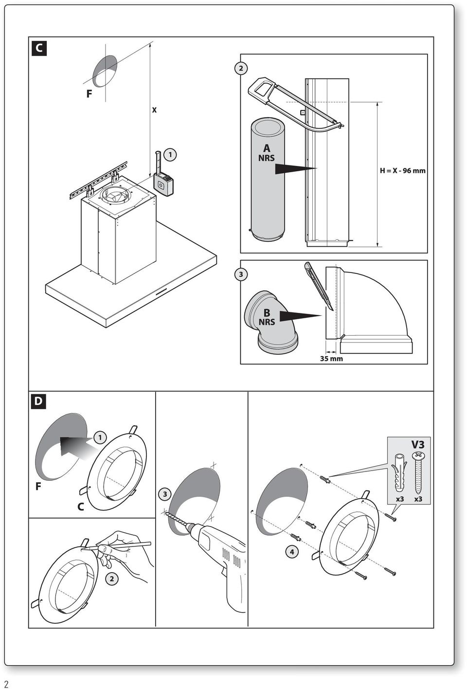
21 M N O 4. PULIZIA INTERNA É vietata la pulizia di parti elettriche o parti relative al moto re all interno della cappa, con liquidi o solventi. Non usare prodotti contenenti abrasivi. Effettuare tutte queste operazioni scollegando preven tivamente l apparecchio dalla rete elettrica. SICUREZZA AVVERTENZE L impianto elettrico è munito di collegamento a terra secondo le norme di sicurezza internazionali; è inoltre conforme alle normative Europee sull antidisturbo radio. Non collegare l apparecchio a condotti di scarico dei fumi prodotti dalla combustione (caldaie, caminetti,ecc). Verificare che la tensione di rete corrisponda a quella riportata dalla targhetta posta all interno della cappa. La distanza minima di sicurezza tra il piano di cottura e la cappa deve essere di almeno 65 cm. Non fare cotture a fiamma libera sotto la cappa. Controllare le friggitrici durante l uso: I olio surriscaldato potrebbe infiammarsi. - Assicurarsi che vi sia una adeguata ventilazione nella stanza se la cappa è utilizzata con altri apparecchi che utilizzano combustibili come gas o altro. - Non accendere fiamme libere sotto la cappa. - Non collegare l apparecchio a condotti di scarico dei fumi prodotti dalla combustione (caldaie, caminetti, ecc). - Assicurarsi che tutte le normative vigenti sullo scarico dell aria all esterno del locale siano rispettate prima dell utilizzo della cappa. Prima di procedere a qualsiasi operazione di pulizia o di manutenzione, disinserire l apparecchio togliendo la spina o agendo sull interruttore generale. La casa costruttrice declina ogni responsabilità per eventuali danni che possano, direttamente o indirettamente, essere causati a persone, cose ed animali domestici in conseguenza alla mancanza di tutte le prescrizioni indicate nell apposito libretto istruzioni e concernenti, specialmente, le avvertenze in tema di installazione, uso e manutenzione dell apparecchio. GARANZIA La sua nuova apparecchiatura è coperta da garanzia. Le condizioni di garanzia sono riportate per esteso sull ulti ma pagina di copertina di questo libretto. La casa costruttrice non risponde delle possibili ine sattezze, imputabili ad errori di stampa o di trascrizio ne, contenute nel presente libretto. Si riserva di appor tare ai propri prodotti quelle modifiche che ritenesse necessarie o utili, anche nell interesse dell utenza, senza pregiudicare le caratteristiche essenziali di fun zionalità e di sicurezza. ISTRUZIONI MONTAGGIO CAPPE O1 CAPPE PARETE HORIZON NRS, LUMINA NRS, PLANE NRS, VELA NRS Fase 1 (Fig. A) 1) Appoggiare alla parete la barra di sostegno (S) ad un altezza H dal piano cottura determinata dalla somma delle quote: X + Y mm. 2) Controllare con una bolla di livello l allineamento orizzontale; 3) segnare alle estremità della barra di sostegno 2 punti di foratura. 4) Forare, inserire n 2 tasselli ad espansione ø 8mm e fissare la barra di sostegno (S) con le relative viti (V1). 19
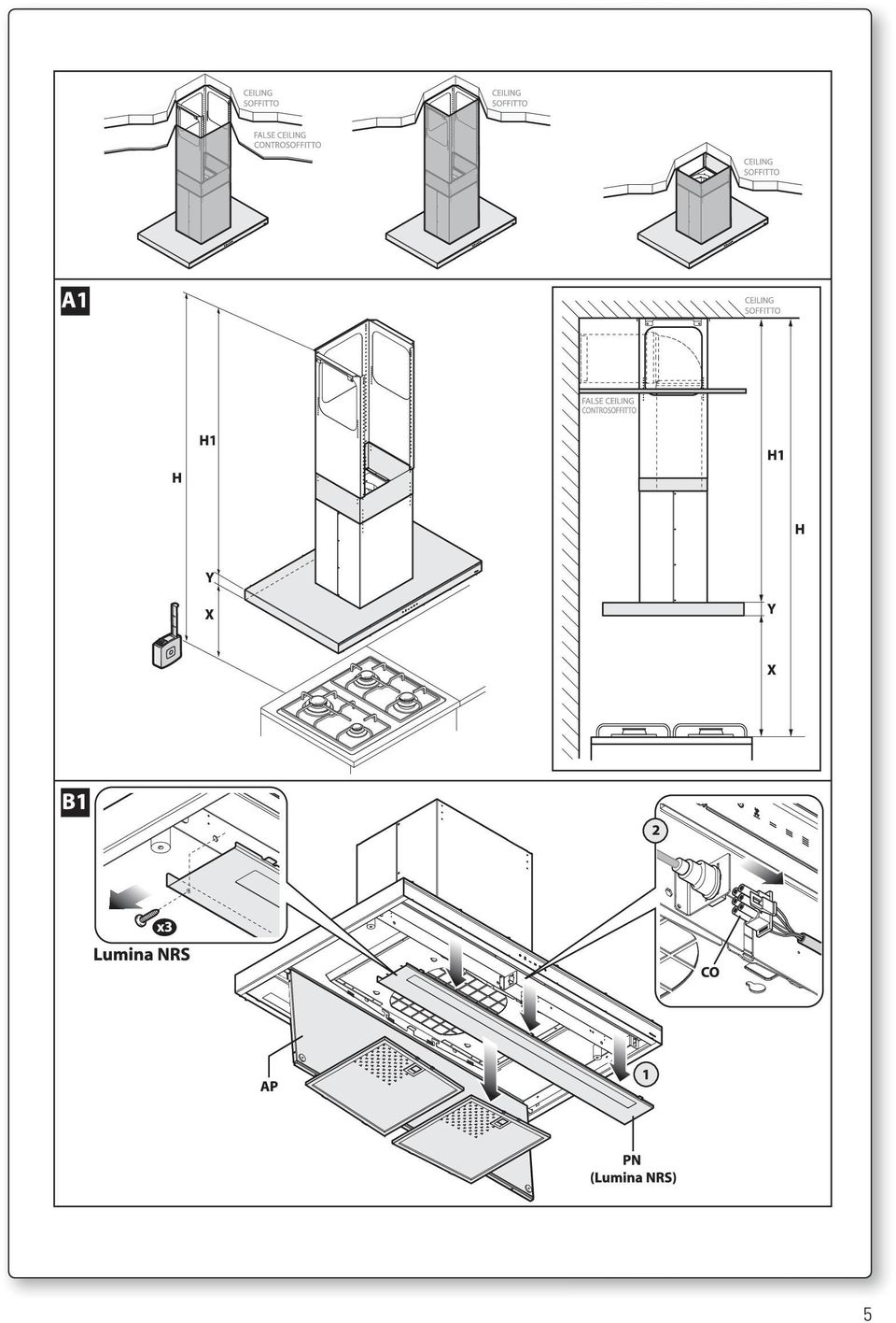
22 20 (Fig. B) 1) Agganciare la cappa alla barra di sostegno (S). 2) Regolare l allineamento della cappa tramite le viti delle attaccaglie. La vite superiore (B) regola la distanza dalla parete, quella inferiore (C) lo scorrimento verticale. 3) Per evitare lo sganciamento della cappa dovuto ad una pressione sottostante, fissarla alla parete con un tassello ad espansione e relativa vite (V2) utilizzando gli appositi fori presenti sul retro della cappa. Fase 2 (Fig. C) - Nel caso di versione aspirante collegare il raccordo di uscita del ventilatore allo scarico esterno (F) seguendo le indicazioni della fig.c. 1) Misurare la quota X come indicato in fig.c part.1. 2) Tagliare il tubo NRS (A) secondo le indicazione della fig.c part.2. 3) Tagliare la curva NRS (B) secondo le indicazioni della fig.c part.3 in modo che il tubo di evacuazione (A) sia installato in pozione perfettamente verticale. (Fig. D) ) Fissare la flangia (C) in corrispondenza del foro di scarico (F) tramite le 3 viti V3. (Fig. E) 1) Inserire accuratamente il tubo (A) nel raccordo motore (D); 2) fissare il tubo (A) al corpo cappa con le 3 viti (V4). 3) Inserire la curva (B) sul tubo (A) e sulla flangia (C). 4) Bloccare la curva (B) al tubo (A) mediante una fascetta e piegare le alette della flangia (C) come indicato in figura. - Eseguire il collegamento elettrico solo dopo aver disinserito l alimentazione elettrica della cappa. Fase 3 (Fig. F) 1) Inserire la prolunga (H) nel camino (G). 2) Fissare l assieme (G+H) al corpo cappa mediante le viti (V5). 3) Fare scorrere la prolunga (H) fino a raggiungere l altezza desiderata. 4) Appoggiare alla parete la staffa (L), controllare con una bolla di livello l allineamento orizzontale e segnare alle estremità n 2 punti di foratura. 5) Forare, inserire n 2 tasselli ad espansione ø 4mm e fissare la staffa (L) con le relative viti (V6). 6) Avvitare con 2 viti (V7) la prolunga (H) alla staffa (L). - Alimentare elettricamente la cappa rispettando le norme vigenti (vedi sezione D del libretto). O2 CAPPE ISOLA HORIZON NRS, LUMINA NRS, PLANE NRS, VELA NRS Fase 1 (Fig. A1) - Individuare l altezza H dal piano cottura determinata dalla somma delle quote: X + Y + H1 (Fig. B1) - Seguendo le indicazioni della sez. H1, rimuovere il pannello aspirazione perimetrale (AP) (se presente) e i filtri metallici. Soltanto nel caso della cappa Lumina NRS Isola, rimuovere anche il pannello (PN) anteriore. - Scollegare il connettore maschio (CO) dal corrispondente connettore femmina fissato sul corpo cappa. (Fig. C1) - Allentare le 4 viti che trattengono la camera motore NRS (CM);
23 - traslare lateralmente la camera motore NRS (CM) in modo che le 4 viti siano posizionate in corrispondenza del foro anziché dell asola; - sollevare la camera motore (CM) verso l alto per rimuoverla dal corpo cappa. (Fig. D1) - Fissare l elemento (TI) alla camera motore NRS (CM) mediante 7 viti (V1). (Fig. E1) - Fissare il traliccio superiore (TS) al soffitto utilizzando 4 tasselli da Ø 8 e relative viti (V2). (Fig. F1 e G1) - Misurare la quota Z come indicato in figura F1. - Tagliare il tubo NRS (A) e la curva NRS (B) secondo le indicazione della figura F1 parte 2, in modo che il tubo di evacuazione (A) sia installato in posizione perfettamente verticale. Fissare la curva NRS (B) sul tubo NRS (A) mediante una fascetta e collegare il tutto in modo provvisorio sul tubo di evacuazione (F) predisposto sul controsoffitto o sul solaio. - Far scorrere l assieme (CM+TI) sul traliccio (TS) fino ad ottenere l altezza desiderata (H1) (vedere anche fig. A1) - Bloccare i componenti (CM+TI e TS) con 8 viti autofilettanti (V3). Fase 2 (Fig. H1) - Inserire accuratamente il tubo NRS (A) nel raccordo motore (D) della camera motore (CM) e bloccarlo con 3 viti (V7). (Fig. I1 e L1) - Fissare gli elementi supporto prolunga (SP) al traliccio (TS) nel caso di controsoffitto o alla camera motore (CM) nel caso non venga utilizzato il traliccio (TS). - Infilare il camino (G) sulla prolunga (H) e bloccarli tra loro con nastro adesivo di carta. - Inserire l assieme camino-prolunga (G+H) nel corpo motore (CM). - Fissare l assieme camino-prolunga (G+H) agli elementi supporto prolunga (SP) o sul traliccio superiore TS tramite le 4 viti metriche M4 (V5) senza avvitarle completamente. (Fig. M1) - Alzare il corpo cappa in modo che i suoi fori inferiori siano centrati sulle 4 viti metriche M5 della camera motore (CM). Traslare lateralmente la camera motore (CM) in modo che le viti metriche si posizionino nelle asole, poi serrarle definitivamente. Fase 3 (Fig. N) - Togliere lo scotch di carta, svitare le 4 viti metriche M4 (V5) avvitate precedentemente agli elementi supporto prolunga (SP) e far scorrere verso il basso l assieme camino-prolunga (G+H). - Effettuare i seguenti collegamenti: SCARICO -> tubo + curva NRS (A+B) al tubo di scarico (F). Nel caso di versione filtrante (vedi sez. F) lo scarico dell aria deve essere indirizzato verso le asole della prolunga. ELETTRICO (solo dopo aver disinserito l alimentazione elettrica). - Fissare nuovamente la prolunga (H) agli elementi supporto prolunga (SP) tramite le 4 viti metriche M4 (V5). - Fare scorrere verso il basso il camino (G) e fissarlo al coropo cappa tramite le viti autofilettanti (V6). - Ricollegare il connettore maschio (CO) al corrispondente connettore femmina fissato nel corpo cappa. - Seguendo le indicazioni della sezione H1, rimontare i filtri metallici e l eventuale pannello aspirazione perimetrale (AP). Nel caso della cappa Lumina NRS isola rimontare anche il pannello (PN) anteriore. - Alimentare elettricamente la cappa rispettando le norme vigenti (vedi sezione D del libretto). 21
24 GB INSTRUCTIONS BOOKLET A WARNINGS This instruction booklet must be kept together with the appliance for future reference. If the appliance is sold or consigned to other parties, check that the booklet is supplied with it, to ensure that the new user has the correct information on the operation of the range hood and is aware of the warnings. These warnings have been provided for the your safety and the safety of others. As a result, please read them carefully before installing and operating the appliance. This appliance is not intended for use by young children or infirm persons unless they have been adequately supervised by a responsible person to ensure that they can use the appliance safely. Young children should be supervised to ensure they do not play with the appliance. The appliance must be installed by qualified personnel, in accordance with the standards in force. If the supply cord is damaged, it must be re-placed by the manufacturer, its service agent or similarly qualified persons in order to avoid a hazard. Any modifications that may be required to the electrical system for the installation of the range hood must only be made by qualified electricians. It is dangerous to modify or attempt to modify the characteristics of this system. In the event of malfunctions or if repairs are required to the appliance, do not attempt to solve the problems directly. Repairs performed by unqualified persons may cause damage. For all repair and other work on the appliance, contact an authorised service/spare parts centre. Always check that all the electrical parts (lights, exhaust device), are off when the appliance is not being used. Read the entire instruction booklet before performing any operations on the range hood. The range hood must only be used for the exhaust of cooking fumes in home kitchens. The manufacturer disclaims all liability for any other use of the appliance. The maximum weight of any object placed above the hood, or hung to it (if possible) must not exceed 1,5 kilos. After installing the stainless steel hood, clean it in order to remove any residue of the protective glue, and stains of grease or oil. The manufacturer recommends its cleaning cloth available for purchase. The manufacturer accepts no liability in case of damage caused by the use of different detergent types. B TECHNICAL SPECIFICATIONS The technical data pertaining to the electric appliance The technical specifications of the appliance are shown on the rating plates located inside the range hood. C INSTALLATION (Section reserved for qualified installers of the range hood) The distance between the hob and the lowest part of the rangehood is normally at least 65 cm. This distance is measuresd in the lowest part of the rangehood not operating at safety voltage. Based on this detail provided by European Standards, the distance may be reduced in some models as specified in the general catalogue. If the instructions for installation for the gas hob 22
25 specify a greater distance, this has to be taken into account. In the outside exhaust version, the diameter of the fume discharge duct must be no smaller than the range hood connection. In the horizontal sections, the duct must slope slightly (around 10%) upwards, so as to better convey the air outside of the room. Avoid using angled pipes, make sure that the pipes are at least of the minimum length. Comply with the current regulations on air discharge into the atmosphere. If a boiler, stove, fireplace, etc. that uses gas or other fuels is being used at the same time, make sure the room where the fumes are extracted is well ventilated, in compliance with the current regulations. Mounting instruction: see section O of the booklet. D ELECTRICAL CONNECTIONS (Section reserved for qualified installers) WARNING! Before doing any work inside the range hood, disconnect the appliance from the mains power supply. Check that the wires inside the range hood are not disconnected or cut; if this is the case, contact your nearest service centre. The electrical connections must be performed by qualified personnel. The connections must be performed in compliance with the legal standards in force. Check that the relief valve and the electrical system are able to support the load of the appliance (see the technical specifications in point B). Some types of appliance are supplied with a cable without plug; in this case, standardised plugs must be used, keeping in mind that: - the yellow-green wire must be used for the earth, - the blue wire must be used for the neutral, - the brown wire must be used for the phase; the cable must not come into contact with hot parts (over 70 C). - fit a plug that is suitable for the load to the power cable, and connect it to a suitable power outlet. For appliances that come supplied with cable and plug please ensure they are plugged into a circuit suitable for this appliance. Please refer to a qualifed person. (See technical specifications in point B). E The manufacturer declines all liability if the safety standards are not observed. RANGE HOOD WITH OUTSIDE DISCHARGE (exhaust) In this version, the fumes and steam from the kitchen are conveyed outside through an exhaust duct. The exhaust conveyor that protrudes from the upper part of the range hood must be connected to a duct that carries the fumes and steam outside. In this version, the charcoal filters, if fitted, should be removed; to do this, see the instructions in point F. There must be adequate ventilation of the room when the range hood is used at the same time as appliances burning gas or other fuels, according to the standard. 23
26 Deviation for Germany: When the range hood and appliances supplied with energy other than electricity are simultaneously in operation, the negative pressure in the room must not exceed 4 Pa (4x10 E-5 bar). F RECIRCULATING RANGE HOOD (with filter) In this model, the area passes through the charcoal filters to be purified and is then recycled into the kitchen environment. See sect. H for assembly. G OPERATION 1. ELECTRONIC CONTROL PANEL (PLANE NRS) Light pushbutton ON: light on (the pushbutton is lit); OFF: light off; Pushbutton - Press to reduce motor speed Speed 1, 2 and 3 are indicated by the number of LEDs that light up (excluding the light and the timer LEDs). Pushbutton + Press to increase motor speed Speed 1, 2 and 3 are indicated by the number of LEDs that light up (excluding the light and the timer LEDs). (In the 4-speed version the pushbutton + blinks. The fourth speed remains on for a set duration of time. After 15 minutes the motor returns to the third speed). Mode pushbutton Function: it turns hood motor on and off. The function desired speed enables to start the motor at the speed that was selected before the hood was last turned off. Optional: version with remote control (some versions only). WARNING: Install the hood away from sources of electromagnetic waves, as these could affect the correct operation of the electronic system. Maximum operating distance: 5 metres. The maximum operating distance could be less than 5 metres in case of electromagnetic interference by other equipment. Light pushbutton on remote control: light on/off. and + pushbutton: increase/decrease speed (to start the motor press either the + or the pushbutton). Timer pushbutton: see instructions below. Timer and filter clogged alarm pushbutton This function allows the automatic turning off of the hood after running for 15 minutes at the speed previously set (the pushbutton shows a flickering light). After about 30 hours of running the pushbutton indicates the need for washing the metal filters (the pushbutton shows a solid red light). To disable the alarm press the pushbutton for a few seconds until the red light turns off. Then turn the hood off and on again to check that the alarm has disappeared. 24
27 2. ELECTRONIC CONTROL PANEL (HORIZON NRS, LUMINA NRS, VELA NRS) 1: Timer/Alarm filters The steady RED light indicates that the fat filter alarm is activated (after 30 hours), to deactivate this alarm and zero the meters, maintain the Key pressed for 3 seconds. Flashing RED light indicates that the timer function is activated. This function can only be activated if the motor is activated and running at any velocity when the Key is pressed (either prolonged or not). This function will cause the automatic switch-off of the hood after 15 minutes. With the Timer function activated, the hood can be switched-off by the operator in any case and the function will be deactivated. The Timer function remains associated to a velocity. A change in the velocity, with the Timer function activated, will deactivate it. 2: 1st Velocity When the LED is switched-off, non-prolonged pressing of the key will switch-on the hood at the 1 st velocity and illuminate the respective LED. The function will switch-on when the Key is released. When the LED is switched-off and another velocity is activated, pressing the Key will imply selection of the 1 st velocity, switching-on of the respective LED and switching-off of the LED associated with the velocity that was previously selected. When the LED is on, pressing the Key will imply the switching-off the LED and MOTOR. When the LED is switched-off, prolonged pressing (at least 3 seconds) of the Key will cause activation of the recirculation function. During the recirculation function (with a duration of 24 hours), the LED will flash. From the activation of this function, the hood will remain switched-on for one hour at the 1 st velocity, after which it will switch-off for 3 hours and then reactivate for another hour. These cycles are repeated until the timeout. With this function activated, the other functions cannot be selected. To remove this function, keep Key 2 pressed for at least 3 seconds. 3: 2nd Velocity When the LED is switched-off and another velocity activated, pressing the Key (either prolonged or not) will imply the selection of the 2 nd velocity, switching-on of the respective LED and switching-off of the LED associated with the velocity that was previously selected. When the LED is switched-off and no velocity activated, pressing the Key will have no effect. When the LED is switched-on, pressing the Key 3 will have no effect. To switch the hood off, it will be necessary to firstly select the 1 st velocity and then repress the same Key. 4: 3rd Velocity When the LED is switched-off and another velocity activated, pressing the Key (either prolonged or not) implies the selection of the 3 rd velocity, the switching-on of the respective LED and switching-off of the LED associated to the velocity that was previously selected. When the LED is switched-off and no velocity activated, pressing the Key will have no effect. When the LED is switched-on, pressing the Key 4 will have no effect. 25
28 To switch the hood off, it will be necessary to firstly select the 1 st velocity and then repress the same Key. 5: 4th Velocity When the LED is switched-off and another velocity activated, pressing the Key (either prolonged or not) implies the selection of the 4 th velocity, switching-on of the respective LED and switching-off of the LED associated to the velocity that was previously selected. When the LED is switched-off and no velocity activated, pressing the Key will have no effect. When the LED is switched-on, pressing the key 5 will have no effect. The forth velocity must remain on for a maximum of 14 minutes, after which, one must return to the third. To switch the hood off, it will be necessary to firstly select the 1 st velocity and then repress the same key. 6: Light - Remote Binding Light: Briefly pressing key T6 will turn the light on and off. The T6 key will light up if the light is on. Remote Binding (optional): With motor and light turned off, applying prolonged pressure on the T6 key will activate remote binding mode. The T6 Key will flash for a maximum of 10 seconds. During flashing, at least one radio control key must be pressed. The function will deactivate upon completion of the 10 seconds, or earlier if a compatible remote control is detected. Key pressure management: Prolonged pressure = finger pressed on key for at least 3 seconds, the function activates during pressure. Non-prolonged pressure = finger pressed on key for less than 3 seconds, the function activates upon its release. Radio control (optional): Place the device far from sources of electromagnetic waves which could interfere with the range hood s electronic functions Maximum operating distance 4 metres. This distance may vary in defect based on electromagnetic interference of other devices. Function of the remote control Light Key - Key + Key Timer Key Code Change (only in case of malfunction) DESCRIPTION Pressing the Light key will switch the light on/off Pressing the - Key will decrease motor speed. If 1 (1st) speed is in gear, pressing the - key will turn off the motor If the motor is turned off, pressing the + key will activate the motor at 1 (1st) speed. If the motor is operating, pressing the + key will increase motor speed up to the maximum. If the motor is active, pressing the timer key will activate/deactivate the timer function Press the Luce (Light) key together with the Timer key of the remote control until the blue LED begins to slowly flash. If the - key of the remote control is pressed within 5 seconds, the new code will be generated and memorised. Memorisation is confirmed by 3 brief flashes of the LED. To return to the default code, apply pressure on the - key together with the + key for over 5 seconds. Memorisation of the default code will be signalled with 3 brief flashes of the LED. Each time that a new code is generated or that the default code is set in the remote control, it is necessary to also carry out the previously described Remote Binding (Light Key of the pushbutton) procedure. 26
29 H I FILTERS REMOVING AND REPLACING S INSTRUCTIONS 1. METAL FILTERS To remove the anti-grease metal filters, just act on the specific handle. In the perimeter suction hoods (horizon nrs, lumina nrs, vela nrs) remove the steel panel as indicated in fig. H3 and then remove the metal filters. 2. CHARCOAL FILTERS To assemble or replace the charcoal filters, see the instructions in the specific optional charcoal filter kit for each model. Plane nrs hood: filter code kacl.921 Horizon nrs 1 motor, lumina nrs hood: filter code (2 per hood) Horizon nrs 2 motor hood: filter code (4 per hood) Vela nrs hood: filter code (1 per hood) To order new charcoal filters, contact your distributor/dealer. ONLY FOR ITALY: Download the filter order module from the website: (access the drop-down assistance menu). LIGHTING ASSEMBLY AND REPLACEMENT WARNING! Light bulbs with different shapes and power ratings from the original may seriously damage the light compartment. 1. SPOTLIGHT How to replace a square halogen light: a) Check that the equipment is disconnected from the power supply. b) Open the panel completely till 90 (see figure) pressing the PUSH button c) Replace the lamp with a similar one (halogen, max 20 W, 12 Volt, G4 connection). d) Close the panel. If the panel does not close correctly repeat the operation at point b. Square halogen light L 2. FLUORESCENT TUBE (Section reserved for qualified installers) Replacing the fluorescent tube: a) Disconnect the device from the mains; b) Unscrew the fixing screws and remove the bottom panel; c) Remove the fluorescent tube, by rotating through 90, and replace it with one of similar features (8W-13W-21W-28W according with the model); d) Reconnect the device to the mains. MAINTENANCE AND CLEANING Constant maintenance ensures the correct operation and efficiency of the appliance over time. Special attention should be paid to the metal grease-trapping filters and the charcoal 27
30 M filters. Frequent cleaning of the filters and their supports will ensure that fats and grease do not accumulate on the range hood, with the consequent risk of fire. 1. METAL GREASE-TRAPPING FILTERS These trap the fat and grease particles suspended in the air, and therefore should be washed every month in hot water and detergent, without bending them. Wait until they are completely dry before repositioning them. To remove and replace these filters, see the instructions in point H1. This operation should be performed at regular intervals. 2. CHARCOAL FILTERS These trap the odours present in the stream of air that passes through them. The air is purified by passing a number of times through the filters and being recirculated into the kitchen. The charcoal filters cannot be cleaned, and should be replaced on average every 3-4 months (according to use). To replace the charcoal filters, see the instructions in point H2. 3. CLEANING THE OUTSIDE OF THE APPLIANCE It is advised to clean the external hood surfaces at least every 15 days in order to avoid that oily or greasy substances affect the steel surfaces. The ouside of the range hhod should be cleaned using a damp cloth and neutral liquid detergent or denatured alcohol. In case of fingerprint-less finish (fasteel) clean only with water and neutral soap using clean with a soft cloth, rinse and wipe dry thoroughly. Do not use products that contain abrasive substances, rough cloths or cloths specifically designed for cleaning steel. Using abrasive substances or rough cloths will inevitably damage the finish of steel. The steel surface will be irrevocably damaged if the instructions above are not complied with. Keep these instructions together with the instructions for use of your hood. The manufacturer accepts no liability for any damage caused by non-compliance with the instructions above. 4. CLEANING THE INSIDE OF THE APPLIANCE The electrical parts or parts of the motor assembly inside the range hood must not be cleaned using liquids or solvents. Do not use abrasive products. All the above operations must be performed after having disconnected the appliance from the mains power supply. SAFETY WARNINGS The electrical system features an earth connection in compliance with international safety standards; furthermore, it is compliant with the European standard for electromagnetic compatibility. Do not connect the appliance to flues (from boilers, fireplaces, etc.). Make sure the mains voltage corresponds to the values on the rating plate located inside the range hood. The minimum safety distance between the cooktop and the range hood must be at least 65 cm. Never cook on open flames under the range hood. Check deep-fryers during use: superheated oil may be flammable. - Ensure there is adequate ventilation of the room when the rangehood is used at the same time as appliances burning gas or other fuels. - Do not flambe under the rangehood - The exhaust air must not be discharged into a flue which is used for exhausting fumes from appliances burning gas or other fuels. - Ensure that all regulations concerning the discharge of exhaust air have been fulfilled before you use the appliance. 28
Cod (LUMINA NRS-PLANE NRS-HORIZON NRS-VELA NRS)
") Cod. 110030290 (LUMINA NRS-PLANE NRS-HORIZON NRS-VELA NRS) LIBRETTO ISTRUZIONI INSTRUCTIONS BOOKLET BEDIENUNGSSANLEITUNG LIVRET D INSTRUCTIONS MANUAL DE INSTRUCCIONES MANUAL DE INSTRUÇÕES àçëíêìäñàü èé
Cod. 110030290 (LUMINA NRS-PLANE NRS-HORIZON NRS-VELA NRS) LIBRETTO ISTRUZIONI INSTRUCTIONS BOOKLET BEDIENUNGSSANLEITUNG LIVRET D INSTRUCTIONS MANUAL DE INSTRUCCIONES MANUAL DE INSTRUÇÕES àçëíêìäñàü èé
Cod (LUMINA NRS-PLANE NRS-HORIZON NRS-VELA NRS) LIBRETTO ISTRUZIONI
 LIBRETTO ISTRUZIONI") Cod. 110030290 (LUMINA NRS-PLANE NRS-HORIZON NRS-VELA NRS) LIBRETTO ISTRUZIONI INSTRUCTIONS BOOKLET BEDIENUNGSSANLEITUNG LIVRET D INSTRUCTIONS MANUAL DE INSTRUCCIONES MANUAL DE INSTRUÇÕES àçëíêìäñàü èé
Cod. 110030290 (LUMINA NRS-PLANE NRS-HORIZON NRS-VELA NRS) LIBRETTO ISTRUZIONI INSTRUCTIONS BOOKLET BEDIENUNGSSANLEITUNG LIVRET D INSTRUCTIONS MANUAL DE INSTRUCCIONES MANUAL DE INSTRUÇÕES àçëíêìäñàü èé
WATER MATTRESS MASSAGE SYSTEM 20439
 Page 1 of 10 WATER MATTRESS MASSAGE SYSTEM 20439 CONTENTS Massage System with Controller Please note: the above image shows a white unit and a blue unit. The white unit is supplied inside the blue unit
Italiano English Deutsch Français Español Portoghese LIBRETTO ISTRUZIONI. Cod (CAPPE AD ISOLA) на русском языке
 на русском языке") LIBRETTO ISTRUZIONI Italiano English Deutsch Français Español Portoghese Cod. 110030252 (CAPPE AD ISOLA) INSTRUCTIONS BOOKLET BEDIENUNGSSANLEITUNG LIVRET D INSTRUCTIONS MANUAL DE INSTRUCCIONES MANUAL DE
LIBRETTO ISTRUZIONI Italiano English Deutsch Français Español Portoghese Cod. 110030252 (CAPPE AD ISOLA) INSTRUCTIONS BOOKLET BEDIENUNGSSANLEITUNG LIVRET D INSTRUCTIONS MANUAL DE INSTRUCCIONES MANUAL DE
IAN 93902 1/22. Washing machine cabinet. Mobile lavatrice Istruzioni per il montaggio. Armario saledizo de máquina lavadora Instrucciones de montaje
 Washing machine cabinet ES PT DE AT CH Armario saledizo de máquina lavadora Instrucciones de montaje Armário para montar por cima da máquina de lavar a roupa Instruções de montagem Waschmaschinenüberbauschrank
VENTILATORI INDUSTRIALI mapi
 VENTILATORI INDUSTRIALI mapi mod.vge. 090605 ma.pi s.a.s. Via F.lli di Dio, 12-20037 PADERNO DUGNANO (Mi) - Tel. 02.9106940 - Fax 02.91084136 email: mail@ma-pi.it www.ma-pi.it VENTILATORI INDUSTRIALI VCN
Italiano English Deutsch Français Español Portoghese LIBRETTO ISTRUZIONI. Cod (CAPPE A PARETE) на русском языке
 на русском языке") Cod. 110030250 (CAPPE A PARETE) LIBRETTO ISTRUZIONI INSTRUCTIONS BOOKLET BEDIENUNGSSANLEITUNG LIVRET D INSTRUCTIONS MANUAL DE INSTRUCCIONES MANUAL DE INSTRUÇÕES àçëíêìäñàü èé ùäëèãìäíäñàà INSTRUKCJE OBSŁUGI
Cod. 110030250 (CAPPE A PARETE) LIBRETTO ISTRUZIONI INSTRUCTIONS BOOKLET BEDIENUNGSSANLEITUNG LIVRET D INSTRUCTIONS MANUAL DE INSTRUCCIONES MANUAL DE INSTRUÇÕES àçëíêìäñàü èé ùäëèãìäíäñàà INSTRUKCJE OBSŁUGI
CHECK DEVICE TRANSPONDER RF REF REF REF 10292
 IT/EN/ES/PT 1/6 CHECK DEVICE TRANSPONDER RF Prodotto da/manufactured by/fabricado por: DIESSE Diagnostica Senese SpA Via delle Rose 10 53035 Monteriggioni (Siena) - Italy Modifiche introdotte nella revisione
LIGHT PANEL CONTENTS Light Panel Power supply Fixtures (brackets, screws)
") Page 1 of 8 LIGHT PANEL 20367 CONTENTS Light Panel Power supply Fixtures (brackets, screws) ABOUT THIS PRODUCT The Light Panel may be used on a table top as a free-standing object, or mounted either horizontally
Page 1 of 8 LIGHT PANEL 20367 CONTENTS Light Panel Power supply Fixtures (brackets, screws) ABOUT THIS PRODUCT The Light Panel may be used on a table top as a free-standing object, or mounted either horizontally
Italiano English Deutsch Français Español Português LIBRETTO ISTRUZIONI. на русском языке
 LIBRETTO ISTRUZIONI Italiano English Deutsch Français Español Português Cod. 110030284 (NUVOLA) INSTRUCTIONS BOOKLET BEDIENUNGSSANLEITUNG LIVRET D INSTRUCTIONS MANUAL DE INSTRUCCIONES MANUAL DE INSTRUÇÕES
Manual de instruções para Sifões VETUS e Johnson Pump
 Manual de instruções para Sifões VETUS e Johnson Pump Em caso dúvidas na instalação após a leitura do manual, favor entrar em contato com nosso departamento técnico através do telefone: (11) 3477-5655
TEST DEVICE 10K REF TEST DEVICE 5 K REF TEST DEVICE 1K REF 10292
 IT/EN/ES/PT 1/6 10K 5 K 1K Prodotto da/manufactured by/fabricado por: DIESSE Diagnostica Senese SpA Via delle Rose 10 53035 Monteriggioni (Siena) - Italy Modifiche introdotte nella revisione corrente Changes
1 WC System. Instrução Técnica Instrucción Técnica Technical Instruction
 WC System . WC SYSTEM Technical characteristics: Electro-pneumatic system The toilet mechanism works with pneumatic energy supplied by the chassis's pneumatic system. The water timer is done by a relay,
SAP911. Acondicionador de aire portátil Ar condicionado portátil Portable Air Conditioner. Manual do utilizador
 ES PT EN SAP911 Acondicionador de aire portátil Ar condicionado portátil Portable Air Conditioner ES Manual del usuario PT Manual do utilizador EN User Manual ES Gracias por elegir este acondicionador
Operator Manual Thermoplan AG, Subject to change REV-0
 1 Overview Control panel Foamer head Cup platform Liner pouch 8 Overview Heating basin Milk foam tube Level controller Milk container Cover Hood 9 Putting into operation Plug the appliance into a suitable
START HERE PTB: COMECE AQUI FRA: MISE EN ROUTE ITA: PER COMINCIARE PTG: INICIAR AQUI ESP: EMPEZAR AQUÍ
 START HERE PTB: COMECE AQUI FRA: MISE EN ROUTE ITA: PER COMINCIARE PTG: INICIAR AQUI ESP: EMPEZAR AQUÍ Install the software (required for full webcam functionality). Instale o software (necessário para
Security Kit. Security Kit. Security Kit. Security Kit. See Reverse Side For Security Installation Instructions 8811-000008
 Security Kit Security Kit See Reverse Side For 8811-000008 See Reverse Side For 8811-000008 Security Kit Security Kit See Reverse Side For 8811-000008 See Reverse Side For 8811-000008 1. Using security
VGM. VGM information. ALIANÇA VGM WEB PORTAL USER GUIDE June 2016
 Overview The Aliança VGM Web portal is an application that enables you to submit VGM information directly to Aliança via our e-portal Web page. You can choose to enter VGM information directly, or to download
Italiano English Deutsch Français Español Portoghese LIBRETTO ISTRUZIONI. на русском языке
 LIBRETTO ISTRUZIONI Italiano English Deutsch Français Español Portoghese Cod. 110030238 (QUASAR) INSTRUCTIONS BOOKLET BEDIENUNGSSANLEITUNG LIVRET D INSTRUCTIONS MANUAL DE INSTRUCCIONES MANUAL DE INSTRUÇÕES
EURO CHILLER INTERNATIONAL COOLING. Minichill-Termochill
 EURO L idea di poter termoregolare uno stampo raggruppando le funzioni di riscaldamento o raffreddamento in un unica macchina è quella che ha spinto Eurochiller alla produzione del Minichill e Termochill.
CONS2/CONS3. User manual - Release 2.0
 CONS2/CONS3 Console da banco per display eliminacode Tabletop console for take-a-number display Consola de mesa para pantalla de turno Terminal d appel pour afficheur des files d attente Console de mesa
PRODUCT FAMILY DATASHEET SubstiTUBE PURE
 SubstiTUBE PURE Economic LED tubes for electromagnetic control gears AREAS OF APPLICATION Corridors, stairways, parking garages Cooling and storage rooms Warehouses Domestic applications General illumination
ATC ROC. G 100 IE-XIE Confort & G 100 IE-XIE/GTA Confort. D Gasheizkessel Betriebs-, Reinigungs- und Wartungsanleitung für den BENUTZER Seite...
 G 00 IE-XIE Confort & G 00 IE-XIE/GTA Confort E Calderas de gas Instrucciones de Funcionamiento, Limpieza y Mantenimiento para el USUARIO Página... 5 GB Gas Boilers Operating, Cleaning, and Maintenance
Motor PTC Kit. Kit PTC del Motor. Kit PTC do Motor SSW-07 / SSW-08
 Motors Automation Energy Transmission & Distribution Coatings Motor PTC Kit Kit PTC del Motor Kit PTC do Motor SSW-07 / SSW-08 Installation, Configuration and Operation Guide Guía de Instalación, Configuración
Operação de Instalações Marítimas
 ENIDH, Abril 2011 Sumário 1 Steering Gear 2 Bow Thrust 3 Propeller Servo 1 Steering Gear 2 Bow Thrust 3 Propeller Servo Steering Gear System Comprises two identical hydraulic systems. Each system includes:
Italiano English Deutsch Français Español Português LIBRETTO ISTRUZIONI. Cod (DOWNDRAFT EVO) на русском языке
 на русском языке") Cod. 110030279 (DOWNDRAFT EVO) LIBRETTO ISTRUZIONI INSTRUCTIONS BOOKLET BEDIENUNGSSANLEITUNG LIVRET D INSTRUCTIONS MANUAL DE INSTRUCCIONES MANUAL DE INSTRUÇÕES àçëíêìäñàü èé ùäëèãìäíäñàà INSTRUKCJE OBSŁUGI
Cod. 110030279 (DOWNDRAFT EVO) LIBRETTO ISTRUZIONI INSTRUCTIONS BOOKLET BEDIENUNGSSANLEITUNG LIVRET D INSTRUCTIONS MANUAL DE INSTRUCCIONES MANUAL DE INSTRUÇÕES àçëíêìäñàü èé ùäëèãìäíäñàà INSTRUKCJE OBSŁUGI
Desumidificador de ar
 MANUAL DO USUÁRIO USER MANUAL Desumidificador de ar Baby Care Português 4// Manual do Usuário Parabéns! Você acaba de adquirir mais um produto com a qualidade Multilaser! O Desumidificador de Ar Multilaser
Instalação do encosto. Recursos. Como usar os tubos adaptadores. Estrutura do produto. Sistema de Som
 MANUAL Instalação do encosto Sistema de Som Recursos Disponível em preto, cinza Hastes de montagem ajustáveis para encaixe em qualquer assento Hastes ajustáveis a partir de 4 polegadas de distância a 8
User Guide Manual de Utilizador
 2400 DPI OPTICAL GAMING MOUSE User Guide Manual de Utilizador 2014 1Life Simplify it All rights reserved. www.1-life.eu 2 2400 DPI OPTICAL GAMING MOUSE ENGLISH USER GUIDE...4 MANUAL DE UTILIZADOR PORTUGUÊS...18
1. DESCARGA DEL SOFTWARE DE BLUETOOTH EN EL SMARTPHONE
 MANUAL DEL USUARIO PARA BLUETOOTH ES 1. DESCARGA DEL SOFTWARE DE BLUETOOTH EN EL SMARTPHONE Entre en Apple Store o Google Play y busque: - BH Premium - BH Lite BH Premium BH Lite 2. FIJACIÓN DEL MÓDULO
hdd enclosure caixa externa para disco rígido
 hdd enclosure caixa externa para disco rígido USER S GUIDE SPECIFICATONS HDD Support: SATA 2.5 Material: Aluminium and plastics Input connections: SATA HDD Output connections: USB 3.0 (up to 5.0Gbps)
GEAR PUMPS RECOMMENDATIONS BEFORE START-UP
 GEAR PUMPS RECOMMENDATIONS BEFORE START-UP CTI Gear pumps recommendations before start-up 0811-0 Attention: The application of ABER gear pumps must follow all the instructions hereby mentioned in order
Manual de instruções para Caixa Coletora Johnson Pump
 Manual de instruções para Caixa Coletora Johnson Pump Em caso dúvidas na instalação após a leitura do manual, favor entrar em contato com nosso departamento técnico através do telefone: (11) 3477-5655
PHAROS Zelios 12-18 - 25-35. Manuale d'uso per l'utente Questo libretto è destinato agli apparecchi installati in Italia
 Manuale d'uso per l'utente Questo libretto è destinato agli apparecchi installati in Italia Manual de Usuario El presente manual es aplicable a los aparatos instalados en España Manual de utilização para
ÍNDICE PORTUGUÊS INDEX ENGLISH
 ÍNDICE PORTUGUÊS 1. Introdução...2 2. Características...2 3. Avisos...3 4. Instalação...3 4.1 Alimentação por pilha AAA 4.2 Alimentação pela entrada USB 5. Utilizando o Produto...5 6. Solução de Problemas...5
SATA 3.5. hd:basic. hdd enclosure caixa externa para disco rígido
 SATA 3.5 hd:basic hdd enclosure caixa externa para disco rígido hd:basic USER S GUIDE SPECIFICATIONS HDD support: SATA 3.5 Material: Aluminium Input connections: SATA HDD Output connections: USB 2.0
ITALIANO. Presso il rivenditore, sul sito www.edilkamin.com o al numero verde può trovare il nominativo del Centro Assistenza più vicino.
 NELLY I Installazione, uso e manutenzione pag. 2 UK Installation, use and maintenance pag. 22 F Installation, usage et maintenance pag. 42 E Instalación, uso y mantenimiento pag. 62 D Installations-, Betriebs-
1,55m or 1,25m (if portable 1,58m or 1,28m)
") www.portcril.com 1,55m or 1,25m (if portable 1,58m or 1,28m) Information Dimensões / Dimentions Peso sem água / Weight without water Peso com água / Weight with water Capacidade / Capacity 4,20x2,32x1,55m
www.portcril.com 1,55m or 1,25m (if portable 1,58m or 1,28m) Information Dimensões / Dimentions Peso sem água / Weight without water Peso com água / Weight with water Capacidade / Capacity 4,20x2,32x1,55m
A machine that blows bubbles at the press of your switch (not included)
") 1. Product Name Bubbles 2. Product Code 20139 3. Colour As shown 4. Brief Description A machine that blows bubbles at the press of your switch (not included) 5. Contents Bubbles machine with cable attached
1. Product Name Bubbles 2. Product Code 20139 3. Colour As shown 4. Brief Description A machine that blows bubbles at the press of your switch (not included) 5. Contents Bubbles machine with cable attached
Nome empresa: Criado por: Telefone:
 Texto da proposta Data: 22-1-216 SCALA2 3-45 A Grundfos SCALA2 is a fully integrated, self-priming, compact waterworks for pressure boosting in domestic applications. SCALA2 incorporates integrated speed
1. Product Name. 2. Product Code. 3. Colour. 4. Brief Description. 5. Contents. Hip Hop Jumping Cushion. Colours may vary
 1. Product Name Hip Hop Jumping Cushion 2. Product Code 19229 3. Colour Colours may vary 4. Brief Description Provides hours of healthy fun for children. Has a strong padding and has no frame or edges.
Kit Tecsystem for MVW-01. Kit Tecsystem para MVW-01. Kit Tecsystem Installation, Configuration and Operation Guide
 Kit Tecsystem for MVW0 Kit Tecsystem para MVW0 Kit Tecsystem Installation, Configuration and Operation Guide Kit Tecsystem Guía de Instalación, Configuración y Operación Kit Tecsystem Guia de Instalação,
Motors Automation Energy Transmission & Distribution Coatings. Bluetooth Communication Module. Módulo de Comunicación Bluetooth
 Motors Automation Energy Transmission & Distribution Coatings Bluetooth Communication Module Módulo de Comunicación Bluetooth Módulo de Comunicação Bluetooth CFW100 Installation, Configuration and Operation
2/4 BD8201FM. Lot No. REV. A
 1/4 2/4 BD8201FM Lot No. 3/4 Ω Function Description 4/4 Appendix Notes No technical content pages of this document may be reproduced in any form or transmitted by any means without prior permission of
NORMAS DE FUNCIONAMENTO DOS CURSOS DE LÍNGUAS (TURMAS REGULARES E INTENSIVAS) 2015/2016
 2015/2016") NORMAS DE FUNCIONAMENTO DOS CURSOS DE LÍNGUAS (TURMAS REGULARES E INTENSIVAS) 2015/2016 1. Tipos de turma e duração: O CLECS oferece dois tipos de turma: regular e intensivo. Além destas turmas, o CLECS
NORMAS DE FUNCIONAMENTO DOS CURSOS DE LÍNGUAS (TURMAS REGULARES E INTENSIVAS) 2015/2016 1. Tipos de turma e duração: O CLECS oferece dois tipos de turma: regular e intensivo. Além destas turmas, o CLECS
Torre Purificadora de Ar MCP-
 Filtro de cartuchos compacto com pulsos de limpeza A torre de purificação de ar MCP-16 RC é um filtro de cartuchos compacto para limpeza e reciclagem do ar interior. A unidade filtrante compacta é fornecida
Versão: 1.0. Segue abaixo, os passos para o processo de publicação de artigos que envolvem as etapas de Usuário/Autor. Figura 1 Creating new user.
 Órgão: Ministry of Science, Technology and Innovation Documento: Flow and interaction between users of the system for submitting files to the periodicals RJO - Brazilian Journal of Ornithology Responsável:
1. Dados Técnicos...3. 2. Utilização...3. 3. Local de Uso...3. 4. Validade...3. 5. Instruções de Uso...3. 6. Indicações de Segurança...
 SUMÁRIO PORTUGUÊS 1. Dados Técnicos...3 2. Utilização...3 3. Local de Uso...3 4. Validade...3 5. Instruções de Uso...3 6. Indicações de Segurança...4 7. Local de Uso...4 8. Manutenção...4 9. Resolução
DONKEY 19689. 2. Using a small cross-head (positive) screwdriver, undo the screw that secures the battery compartment door. Copyright ROMPA Ltd
 screwdriver, undo the screw that secures the battery compartment door. Copyright ROMPA Ltd") DONKEY 19689 CONTENTS 1 x switch-adapted Donkey This product requires, but does not include, 3 AA batteries and a switch See www.rompa.com for a comprehensive range of switches BEFORE USE 1. Locate the
DONKEY 19689 CONTENTS 1 x switch-adapted Donkey This product requires, but does not include, 3 AA batteries and a switch See www.rompa.com for a comprehensive range of switches BEFORE USE 1. Locate the
SMÅKOKA GB IT PT ES GR IE
 SMÅKOKA GB IT PT ES GR GB IT PT ES GR IE GB IT PT ES GR IE ENGLISH 4 ITALIANO 20 PORTUGUÊS 37 ESPAÑOL 53 ΕΛΛΗΝΙΚΑ 69 Language, Lingua, Idioma, Idioma, Γλώσσα Country, Paese, País, País, Χώρα ENGLISH 4
Aqui pode escolher o Sistema operativo, e o software. Para falar, faça download do Cliente 2.
 TeamSpeak PORTUGUES ENGLISH Tutorial de registo num servidor de TeamSpeak Registration tutorial for a TeamSpeak server Feito por [WB ].::B*A*C*O::. membro de [WB ] War*Brothers - Non Dvcor Dvco Made by:
Miniature Solenoid Valve Type 200
 2/2-Way, Direct-acting, G1/8 - M5 Advantages/Benefits Normally closed Body materials: brass, stainless steel Short response time Compact design Design/Function Applications is a direct-acting plungertype
Memory Module MMF-02. Modulo de Memoria MMF-02. Módulo de Memória MMF-02 CFW70X
 Motors Automation Energy Transmission & Distribution Coatings Memory Module MMF-02 Modulo de Memoria MMF-02 Módulo de Memória MMF-02 CFW70X Installation, Configuration and Operation Guide Guía de Instalación,
100 touch. à πƒπ π πø Ã TM TM π TMÀ
 100 touch It Uso e manutenzione ES MANUAL DE USO Y MANTENIMIENTO en Use and maintenance PT MANUAL DE USO E MANUTENÇÃO fr de Manuel d instructions pour l emploi Bedienungs- und wartungsanleitung EL à πƒπ
100 touch It Uso e manutenzione ES MANUAL DE USO Y MANTENIMIENTO en Use and maintenance PT MANUAL DE USO E MANUTENÇÃO fr de Manuel d instructions pour l emploi Bedienungs- und wartungsanleitung EL Ã πƒπ
Accessing the contents of the Moodle Acessando o conteúdo do Moodle
 Accessing the contents of the Moodle Acessando o conteúdo do Moodle So that all the available files in the Moodle can be opened without problems, we recommend some software that will have to be installed
LIBRETTO ISTRUZIONI INSTRUKCJE OBSŁUGI. Cod (POLAR)
") LIBRETTO ISTRUZIONI Cod. 110030237 (POLAR) INSTRUCTIONS BOOKLET BEDIENUNGSSANLEITUNG LIVRET D INSTRUCTIONS MANUAL DE INSTRUCCIONES MANUAL DE INSTRUÇÕES àçëíêìäñàü èé ùäëèãìäíäñàà INSTRUKCJE OBSŁUGI Ed.
LIBRETTO ISTRUZIONI Cod. 110030237 (POLAR) INSTRUCTIONS BOOKLET BEDIENUNGSSANLEITUNG LIVRET D INSTRUCTIONS MANUAL DE INSTRUCCIONES MANUAL DE INSTRUÇÕES àçëíêìäñàü èé ùäëèãìäíäñàà INSTRUKCJE OBSŁUGI Ed.
75, 8.º DTO 1250-068 LISBOA
 EAbrief: Medida de incentivo ao emprego mediante o reembolso da taxa social única EAbrief: Employment incentive measure through the unique social rate reimbursement Portaria n.º 229/2012, de 03 de Agosto
Ewpe Smart App Operation Manual
 Ewpe Smart App Operation Manual Control Flow Chart intelligent home appliances Home Wi-Fi Cellular/ Other Wi-FI Home wireless router Home Wi-Fi APP Operating Systems Requirement for User's smart phone:
PT P.42 NL P.22 IT P.2 SCPH-35004 GT
 3-070-918-51(1) Italiano IT P.2 Nederlands NL P.22 Português PT P.42 Manuale di istruzioni Grazie per avere acquistato il sistema informatico di intrattenimeno PlayStation 2. Tramite la presente console
A Aviação no Comércio Europeu de Licenças de Emissão Especificidades para pequenos emissores
 A Aviação no Comércio Europeu de Licenças de Emissão Especificidades para pequenos emissores Departamento de Alterações Climáticas, Ar e Ruído (DACAR) Divisão de Poluição Atmosférica e Alterações Climáticas
PT P.58 NL P.30 IT P.2 SCPH-50004 SS
 Italiano IT P.2 Nederlands NL P.30 Português PT P.58 Manuale di istruzioni Grazie per avere acquistato il sistema digitale di intrattenimento PlayStation 2. Tramite il presente sistema è possibile utilizzare
Easy Linux! FUNAMBOL FOR IPBRICK MANUAL. IPortalMais: a «brainware» company www.iportalmais.pt. Manual
 IPortalMais: a «brainware» company FUNAMBOL FOR IPBRICK MANUAL Easy Linux! Title: Subject: Client: Reference: Funambol Client for Mozilla Thunderbird Doc.: Jose Lopes Author: N/Ref.: Date: 2009-04-17 Rev.:
de lo normal. A continuación, póngase en contacto con un electricista cualificado. Los datos antes mencionados podrán modificarse sin previo aviso par
 de lo normal. A continuación, póngase en contacto con un electricista cualificado. Los datos antes mencionados podrán modificarse sin previo aviso para introducir mejoras en el producto. 12 Limpar
LIVSLÅGA GB IT PT ES GR IE
 LIVSLÅGA GB IT PT ES GR GB IT PT ES GR IE GB IT PT ES GR IE ENGLISH 4 ITALIANO 20 PORTUGUÊS 37 ESPAÑOL 53 ΕΛΛΗΝΙΚΑ 69 Language, Lingua, Idioma, Idioma, Γλώσσα Country, Paese, País, País, Χώρα ENGLISH
 B A B A 31 30 29 28 1 2 3 4 CON3 Mot 2 CON2 5 BLU ROSSO MARRONE VERDE BIANCO CABLAGGI INTERNI PREDISPOSTI IN FABBRICA 6 SPIA CANCELLO APERTO 24V 15w ELETTROSERRATURA art.110 RG58 * ATTENZIONE: Nel caso
1. Product Name. 2. Product Code. 3. Colour. 4. Brief Description. 5. Contents. Switch Adapted Clip On Fan. Colours may vary
 1. Product Name Switch Adapted Clip On Fan 2. Product Code 20489 3. Colour Colours may vary 4. Brief Description Connects to your switch for switch activation. 5. Contents Fan with cable with 3.5mm jack
INDICE ITALIANO. La scrivente EDILKAMIN S.p.A. con sede legale in Via Vincenzo Monti 47-20123 Milano - Cod. Fiscale P.
 DAISY Termostufa ventilata a pellet - Ventilated pellet stove Thermopoêle ventilé à granulés - Termoestufa ventilada de pellet - Belüfteter wassergeführter Pellets-Heizofen - Geventileerde pelletthermokachel
WI FI INTERACTIVE MAT SWITCH SET 19939
 Page 1 of 6 WI FI INTERACTIVE MAT SWITCH SET 19939 CONTENTS 1 x Control Box with 9V battery 9 x carpet switches: 1 x pink vinyl 1 x purple carpet 1 x blue non-slip mat 1 x green Soft & Silky 1 x light
Italiano English Deutsch Français Español Português. Cod (GRUPPO INCASSO EVO + NRS) LIBRETTO ISTRUZIONI.
 LIBRETTO ISTRUZIONI.") Cod. 110030258 (GRUPPO INCASSO EVO + NRS) LIBRETTO ISTRUZIONI INSTRUCTIONS BOOKLET BEDIENUNGSSANLEITUNG LIVRET D INSTRUCTIONS MANUAL DE INSTRUCCIONES MANUAL DE INSTRUÇÕES àçëíêìäñàü èé ùäëèãìäíäñàà INSTRUKCJE
Cod. 110030258 (GRUPPO INCASSO EVO + NRS) LIBRETTO ISTRUZIONI INSTRUCTIONS BOOKLET BEDIENUNGSSANLEITUNG LIVRET D INSTRUCTIONS MANUAL DE INSTRUCCIONES MANUAL DE INSTRUÇÕES àçëíêìäñàü èé ùäëèãìäíäñàà INSTRUKCJE
SONDA DE ÁGUA QUENTE SANITÁRIA
 SONDA DE ÁGUA QUENTE SANITÁRIA PT Avisos preliminares Estas instruções são parte integrante do manual do aparelho no qual o KIT é instalado. Consulte este manual para as ADVERTÊNCIAS GERAIS e REGRAS FUNDAMENTAIS
DALI TECHNOLOGY. Sistemas e Planeamento Industrial DOMÓTICA. Eng.º Domingos Salvador dos Santos.
 Sistemas e Planeamento Industrial DOMÓTICA DALI TECHNOLOGY Eng.º Domingos Salvador dos Santos email:dss@isep.ipp.pt October 2017 Table of Contents DALI System DALI Field Devices DALI Controllers Topologies
PROCEDIMENTOS NECESSÁRIOS ANTES DE UTILIZAR O EQUIPAMENTO. Instalação do Rasther PC. Habilitação das Montadoras
 Guia Rápido Rasther PC PROCEDIMENTOS NECESSÁRIOS ANTES DE UTILIZAR O EQUIPAMENTO Antes de iniciar o uso do Rasther, será necessário instalar o programa Rasther PC, habilitar as montadoras adquiridas juntamente
INDICE ITALIANO. La scrivente EDILKAMIN S.p.A. con sede legale in Via Vincenzo Monti 47-20123 Milano - Cod. Fiscale P.
 IDROSALLY Termostufa a pellet - Pellet Boiler-stove Thermopoêle à pellets - Termoestufa de pellet Wassergeführte Pellets-Heizofen - Thermokachel met pellet Pelletvarmeovnene - Caldeiras térmicas a pellet
ÍNDICE PORTUGUÊS INDEX ENGLISH
 ÍNDICE PORTUGUÊS 1. Características... 2 2. Conteúdo da Embalagem... 3 3. Como usar o Receptor de TV Digital... 3 4. Tela de Vídeo... 6 5.Requisitos Mínimos... 6 6. Marcas Compatíveis... 8 INDEX ENGLISH
1. Product Name. 2. Product Code. 3. Colour. 4. Brief Description. 5. Contents. 6. Snoezelen Stimulations. 7. Best Use
 1. Product Name Mood Cushion with infra red remote control 2. Product Code 20425 3. Colour White fur, internal light colour can be selected via the remote. 4. Brief Description An extremely lightweight
Seu manual do usuário JURA COMPRESSOR COOLER PRO http://pt.yourpdfguides.com/dref/2468329
 Você pode ler as recomendações contidas no guia do usuário, no guia de técnico ou no guia de instalação para JURA COMPRESSOR COOLER PRO. Você vai encontrar as respostas a todas suas perguntas sobre a JURA
LIBRETTO ISTRUZIONI piani cottura ad incasso. INSTRUCTIONS BOOKLET built-in cooktops. NOTICE D'INSTRUCTIONS plans de cuisson à encastrer
 LIBRETTO ISTRUZIONI piani cottura ad incasso INSTRUCTIONS BOOKLET built-in cooktops NOTICE D'INSTRUCTIONS plans de cuisson à encastrer GEBRAUCHSANWEISUNGEN Kochmulden MANUAL DE INSTRUCCIONES planos de
SALVAPIANTE TREE-GRILLES GRILLES D ARBRE GRELHASPARACALDEIRAS ALCORQUES
 SALVAPIANTE TREE-GRILLES GRILLES D ARBRE GRELHASPARACALDEIRAS ALCORQUES LITTERA - FLORA - STELO - GEMMA 322-323/ BETULLA 324/ MAGNOLIA 325/ PERLA-C 326/ PERLA-Q 327/ OBRA-C 328-329/ OBRA-R 330/ 322 LITTERA
DEPARTAMENTO DE ENGENHARIA CIVIL E ARQUITETURA
 SCHOOL YEAR 01/013 1 ST EXAM 013/01/16 08h00 DURATION: h00 THEORY QUESTIONS (maximum 45 minutes) 1. In a pumped trunk main system explain why the smallest technically viable diameter may not be the least
PHAROS Zelios 12-18 - 25-35
 Istruzioni tecniche per l'installazione e la manutenzione Questo libretto è destinato agli apparecchi installati in Italia Instrucciones de instalación y de utilización El presente manual es aplicable
Motors Automation Energy Transmission & Distribution Coatings. Bluetooth Communication Module. Módulo de Comunicación Bluetooth
 Motors Automation Energy Transmission & Distribution Coatings Bluetooth Communication Module Módulo de Comunicación Bluetooth Módulo de Comunicação Bluetooth CFW100 Installation, Configuration and Operation
30344 Black Box. Instruções de montagem e modo de utilização Istruzioni per il montaggio e l uso
 30344 Black Box Instruções de montagem e modo de utilização Istruzioni per il montaggio e l uso 2 Instruções de montagem e modo de utilização Reservados os direitos de alterações técnicas e no design Istruzioni
Italiano English Deutsch Français Español Português LIBRETTO ISTRUZIONI. Cod (CAPPE AIRMEC) на русском языке
 на русском языке") Cod. 110030287 (CAPPE AIRMEC) LIBRETTO ISTRUZIONI INSTRUCTIONS BOOKLET BEDIENUNGSSANLEITUNG LIVRET D INSTRUCTIONS MANUAL DE INSTRUCCIONES MANUAL DE INSTRUÇÕES àçëíêìäñàü èé ùäëèãìäíäñàà INSTRUKCJE OBSŁUGI
Cod. 110030287 (CAPPE AIRMEC) LIBRETTO ISTRUZIONI INSTRUCTIONS BOOKLET BEDIENUNGSSANLEITUNG LIVRET D INSTRUCTIONS MANUAL DE INSTRUCCIONES MANUAL DE INSTRUÇÕES àçëíêìäñàü èé ùäëèãìäíäñàà INSTRUKCJE OBSŁUGI
PT P.42 NL P.22 IT P.2 SCPH-39004
 3-077-227-32(1) Italiano IT P.2 Nederlands NL P.22 Português PT P.42 Manuale di istruzioni Grazie per avere acquistato il sistema digitale di intrattenimento PlayStation 2. Tramite il presente sistema
QUESTIONARIO DI SODDISFAZIONE DEL FAMILIARE DATI GENERALI. NUCLEO DI APPARTENENZA DEL SUO CONGIUNTO: Dati personali Nome Cognome Residenza
 ALLEGATO 1 Cooperativa Sociale Auxilium Vi.Pa.Vi. rev.0.1 del 07/11/2017 QUESTIONARIO DI SODDISFAZIONE DEL FAMILIARE La preghiamo di rispondere alle seguenti domande per aiutarci a migliorare i nostri
Serviços: API REST. URL - Recurso
 Serviços: API REST URL - Recurso URLs reflectem recursos Cada entidade principal deve corresponder a um recurso Cada recurso deve ter um único URL Os URLs referem em geral substantivos URLs podem reflectir
Protective circuitry, protective measures, building mains feed, lighting and intercom systems
 Tecnologia de instalações electrónicas Training systems / trainers for electrical wiring/building management systems: Protective circuitry, protective measures, building mains feed, lighting and intercom
Temperature module for F4N400
 F4N06 Temperature module for F4N400 Manuale installatore Installation manual LE08294AA-0WP-5W26 2 Temperature module for F4N400 Sommario Operazioni preliminari 4 Presentazione 5 Installazione 6 Utilizzo
APRESENTAÇÃO. ABNT CB-3 Comitê Brasileiro de Eletricidade Comissão de Estudo CE 03:064.01 Instalações Elétricas de Baixa Tensão NBR 5410
 APRESENTAÇÃO ABNT CB-3 Comitê Brasileiro de Eletricidade Comissão de Estudo CE 03:064.01 Instalações Elétricas de Baixa Tensão NBR 5410 Instalações elétricas de baixa tensão NBR 5410:1997 NBR 5410:2004
ATLAS DE ACUPUNTURA VETERINáRIA. CãES E GATOS (EM PORTUGUESE DO BRASIL) BY CHOO HYUNG KIM
 BY CHOO HYUNG KIM") Read Online and Download Ebook ATLAS DE ACUPUNTURA VETERINáRIA. CãES E GATOS (EM PORTUGUESE DO BRASIL) BY CHOO HYUNG KIM DOWNLOAD EBOOK : ATLAS DE ACUPUNTURA VETERINáRIA. CãES E GATOS Click link bellow
Read Online and Download Ebook ATLAS DE ACUPUNTURA VETERINáRIA. CãES E GATOS (EM PORTUGUESE DO BRASIL) BY CHOO HYUNG KIM DOWNLOAD EBOOK : ATLAS DE ACUPUNTURA VETERINáRIA. CãES E GATOS Click link bellow
Novità Nuevo Novo Z 2700 /...
 Novità Nuevo Novo Z 2700 /... Linea di prodotti per l idraulica Programa de productos hidráulicos Programa de hidráulica Con la nuova linea di prodotti per l idraulica HASCO vi offriamo una selezione flessibile
Uma empresa do grupo:
 Rua Horta dos Bacelos, Lt. 18, 3º - 2690-390 Santa Iria de Azóia T: +351 219 533130 F: +351 219 533131 info@hseabra.seabraglobal.com www.seabraglobal.com Uma empresa do grupo: 02 03 Icestop é um sistema
Thank you for using Shepherd 240 Biometric Fingerprint Lock. Please read this Installation Manual carefully before attempting
 Preface Thank you for using Shepherd 240 Biometric Fingerprint Lock Please read this Installation Manual carefully before attempting to install your new lock. This manual covers installation procedures
Caldeira em ferro fundido para funcionamento gás/gásoleo. Caldaia in ghisa per funzionamento gas/gasolio ISTRUZIONI D USO PER L UTENTE
 Apparecchi conformi alla Direttiva Rendimenti 92/42/CEE ed all allegato e del D.P.R. 412-26/08/93. Quando sono abbinati a bruciatori di gas ad aria soffiata con marcatura CE soddisfano anche la Direttiva
Quickstart Guide. WiPry-Pro Combo
 Quickstart Guide CONNECT TO APPLE DEVICE ACCESSORY EXTERNAL TRIGGER 2.4-2.5GHz ANTENNA WARNING DO NOT APPLY MORE THAN 20DBM TO THE ANTENNA WITHOUT EXTERNAL ATTENUATION WARNING DO NOT APPLY MORE THAN -0.5/+3.8V
CODIGOS CONTROLE RS232 Matrix HDMI 4x2 Control EDID/RS232 (GB.42.2014)
") CODIGOS CONTROLE RS232 Matrix HDMI 4x2 Control EDID/RS232 (GB.42.2014) Versão 2014.04.23 Você acaba de adquirir um produto AV LIFE!!! Não deixe de acessar nosso site www.avlife.com.br para ficar por dentro
CODIGOS CONTROLE RS232 Matrix HDMI 4x2 Control EDID/RS232 (GB.42.2014) Versão 2014.04.23 Você acaba de adquirir um produto AV LIFE!!! Não deixe de acessar nosso site www.avlife.com.br para ficar por dentro
heading quick guide 1
 heading quick guide 1 contenuti Grazie per aver acquistato la Drift HD SERVIZIO CLIENTI Controllate il nostro sito ufficiale per aggiornamenti firmware, servizio clienti, novità sui prodotti e video inviati
UPGRADE Engineering Bulletin Dec 02
 MVA Series UPGRADE Engineering Bulletin Dec 0 MVA Surface Mount High CV Vertical Chip Solvent Proof (-6V) 85 C Maximum Temperature Actual Size The MVA series is a general purpose 85 C surface mount capacitor
Métodos Formais em Engenharia de Software. VDMToolTutorial
 Métodos Formais em Engenharia de Software VDMToolTutorial Ana Paiva apaiva@fe.up.pt www.fe.up.pt/~apaiva Agenda Install Start Create a project Write a specification Add a file to a project Check syntax
VC Series Round Vinyl Caps
 1 VC Series Round Vinyl Caps (Round Vinyl Caps) Series VC Caps are extremely flexible and durable protective closures which are ideal for use as thread protectors, dust and moisture seals, pipe and stud