SENSYS. Istruzioni di installazione ed uso Assembly and operation instructions
|
|
|
- Alexandre Medina Damásio
- 7 Há anos
- Visualizações:
Transcrição
1 SENSYS Istruzioni di installazione ed uso Assembly and operation instructions IT INTERFACCIA DI SISTEMA GB SYSTEM INTERFACE FR INTERFACE DE SYSTÈME ES INTERFAZ DE SISTEMA PT INTERFACE DE SISTEMA OK
2 IT indice generalità 3 norme di sicurezza 4 caratteristiche tecniche 5 descrizione prodotto 6 struttura menu 8 impostazione display 10 modalità funzionamento caldaia 12 regolazione temperatura ambiente 13 impostazione acqua calda riscaldamento 14 programmazione oraria riscaldamento 15 funzionamento modalità manuale riscaldamento 18 impostazione acqua calda sanitaria 19 programmazione oraria acqua calda sanitaria 20 funzioni speciali 21 solare & bollitore (se disponibile) 22 area tecnica installazione 23 struttura menu area tecnicna 25 impostazione zona 26 menu configurazione guidata 25 termoregolazione 29 tabella menu 31 tabela codici errori 57 2
3 generalità IT L interfaccia di sistema SENSYS vi permette di dialogare con la caldaia dall ambiente preferito della vostra casa. Potrete così installare la caldaia nel luogo più indicato e comandarla a distanza. L interfaccia di sistema SENSYS vi consente una semplice ed efficace gestione della termoregolazione degli ambienti ed il controllo dell acqua calda sanitaria. Vi fornisce inoltre il primo aiuto, in caso di malfunzionamento della caldaia, segnalando il tipo di anomalia e suggerendo gli interventi per eliminarla o consigliando l intervento del Centro Assistenza. Il presente libretto costituisce parte integrante ed essenziale del prodotto. Leggere attentamente le istruzioni e le avvertenze contenute nel presente libretto in quanto forniscono importanti indicazioni riguardanti l uso e la manutenzione. L installazione, la manutenzione e qualsiasi altro intervento devono essere effettuate da personale in possesso dei requisiti previsti e nel rispetto delle norme vigenti e delle indicazioni fornite dal costruttore. In caso di guasto e/o cattivo funzionamento spegnere l apparecchio e non tentare di ripararlo ma rivolgersi a personale qualificato. Eventuali riparazioni, effettuate utilizzando esclusivamente ricambi originali, devono essere eseguite solamente da tecnici qualificati. Il mancato rispetto di quanto sopra può compromettere la sicurezza dell apparecchio e fa decadere ogni responsabilità del costruttore. Prima di effettuare la pulizia delle parti esterne spegnere l apparecchio. 3
4 IT norme di sicurezza LEGENDA SIMBOLI: Il mancato rispetto dell avvertenza comporta rischio di lesioni, in determinate circostanze anche mortali, per le persone Il mancato rispetto dell avvertenza comporta rischio di danneggiamenti, in determinate circostanze anche gravi, per oggetti, piante o animali Non effettuare operazioni che implichino la rimozione dell apparecchio dalla sua installazione. Danneggiamento dell apparecchio. Non salire su sedie, sgabelli, scale o supporti instabili per effettuare la pulizia dell apparecchio. Lesioni personali per la caduta dall alto o per cesoiamento (scale doppie). Non utilizzare insetticidi, solventi o detersivi aggressivi per la pulizia dell apparecchio. Danneggiamento delle parti in materiale plastico o verniciate. Non utilizzare l apparecchio per scopi diversi da quello di un normale uso domestico. Danneggiamento dell apparecchio per sovraccarico di funzionamento. Danneggiamento degli oggetti indebitamente trattati. Non fare utilizzare l apparecchio da bambini o persone inesperte. Danneggiamento dell apparecchio per uso improprio. ATTENZIONE! L apparecchio non è destinato a essere utilizzato da persone (bambini compresi) le cui capacità fisiche, sensoriali o mentali siano ridotte, oppure con mancanza di esperienza o di conoscenza, a meno che esse abbiano potuto beneficiare, attraverso l intermediazione di una persona responsabile della loro sicurezza, di una sorveglianza o di istruzioni riguardanti l uso dell apparecchio. I bambini devono essere sorvegliati per sincerarsi che non giochino con l apparecchio. QUESTO PRODOTTO È CONFORME ALLA DIRETTIVA EU 2002/96/EC Il simbolo del cestino barrato riportato sull apparecchio indica che il prodotto, alla fine della propria vita utile, dovendo essere trattato separatamente dai rifiuti domestici, deve essere conferito in un centro di raccolta differenziata per apparecchiature elettriche ed elettroniche oppure riconsegnato al rivenditore al momento dell acquisto di una nuova apparecchiatura equivalente. L utente è responsabile del conferimento dell apparecchio a fine vita alle appropriate strutture di raccolta. L adeguata raccolta differenziata per l avvio successivo dell apparecchio dismesso al riciclaggio, al trattamento e allo smaltimento ambientalmente compatibile contribuisce ad evitare possibili effetti negativi sull ambiente e sulla salute e favorisce il riciclo dei materiali di cui è composto il prodotto. Per informazioni più dettagliate inerenti i sistemi di raccolta disponibili, rivolgersi al servizio locale di smaltimento rifiuti, o al negozio in cui è stato effettuato l acquisto. 4
5 caratteristiche tecniche IT Dati tecnici Alimentazione elettrica BUS BridgeNet Assorbimento elettrico max. < 0,5W Temperatura di funzionamento C Temperatura di stoccaggio C Lunghezza e sezione cavo bus NOTA: NEL COLLEGAMENTO TRA SENSORE AMBIENTE E CALDA- IA, PER EVITARE PROBLEMI DI INTERFERENZE, UTILIZZA- RE UN CAVO SCHERMATO O UN DOPPINO TELEFONICO. Memoria tampone 2 h Comformità LVD 2006/95/EC - EMC 2004/108/EC Interferenze elettromagnetiche EN Emissioni elettromagnetiche EN comformità standard EN Sensore temperatura NTC 5 k 1% Grado di risoluzione 0,1 C max. 50 m - min. 0.5 mm² 134 mm 16 mm 96 mm 5
6 IT descrizione del prodotto Tasti e Display: 1. tasto indietro (visualizzazione precedente) 2. manopola 3. tasto OK (conferma l operazione o accede al menu principale) 4. DISPLAY OK Simboli display: - ( ) Estate - ( ) Inverno ( ) OFF caldaia spenta - ( ) Programmazione oraria - ( ) Funzionamento manuale - ( ) Indicazione presenza fiamma - ( ) Temperatura ambiente desiderata - ( ) Temperatura ambiente rilevata - ( ) Temperatura ambiente desiderata deroga - ( ) Temperatura esterna - ( ) Funzione AUTO attiva - ( ) Funzione VACANZA attiva - ( ) Riscaldamento attivo - ( ) Sanitario attivo - ( ) Segnalazione errore 6
7 descrizione del prodotto IT - (COMFORT) Funzione comfort attiva - (1.3 bar) Pressione impianto - ( ) Presenza fiamma - ( ) Solare attivo (ove presente) - ( ) Menu completo: - ( ) Impostazioni riscaldamento - ( ) Impostazioni acqua calda - ( ) Prestazioni sistema - ( ) Opzioni schermo Simboli visibili solo con solare installato: - ( ) Caldaia - ( ) Caldaia in funzione - ( ) Impianto a pavimento - ( ) Bollitore mono serpentino - ( ) Bollitore doppio serpentino - ( ) Bollitore elettrosolare - ( ) Colletore solare - ( ) Circolatore - ( ) Scambiatore - ( ) Valvola deviatrice - ( S1) Sonda collettore - ( S2) Sonda bollitore bassa - ( S3) Sonda bollitore alta - ( S4) Termostato impianto a pavimento - ( ) Sovratemperatura bollitore - ( ) Sovratemperatura collettore - ( ) Funzione antigelo - ( ) Funzione antilegionella - ( ) Funzione recooling - ( ) Visualizzazione display digitale - ( ) Visualizzazione display analogico - ( ) Dispositivo configurabile Prima Accensione La prima volta che si collega l interfaccia di sistema SENSYS alla caldaia, viene chiesto di scegliere alcune impostazioni di base. Come prima cosa è necessario selezionare la lingua dell interfaccia utente. Ruotare la manopola per selezionare la lingua desiderata e premere il tasto OK per confermare. Procedere con l impostazione della data e ora. Ruotare la manopola per selezionare, premere il tasto OK per confermare la selezione, ruotare la manopola per impostare il valore. Premere il tasto OK per confermare. Salvare le impostazione con il tasto OK. Premere il tasto OK per accedere al Menu. Utilizzare la manopola centrale per lo scorrimento della lista menu e la selezione parametri, premere il tasto OK per confermare. ATTENZIONE Alcuni parametri sono protetti da un codice di accesso (codice di sicurezza) che protegge le impostazioni della caldaia da un utilizzo non autorizzato. 7
8 IT struttura menu utente Le funzioni presenti nel dispositivo sono organizzate su tre livelli, in base alla loro importanza e frequenza di utilizzo. 1 Schermata principale 2 Menu impostazioni di base 3 Menu completo Schermata principale Da questo menu è possibile visualizzare lo stato di funzionamento del sistema e modificare la temperatura ambiente desiderata, semplicemente ruotando la manopola Menu impostazioni di base Da questo menu è possibile accedere alle funzioni principali: scelta tra modalità programmazione o manuale e modalità di funzionamento (estate/inverno/ off) Menu completo Da questo menu è possibile accedere a tutti i principali parametri del sistema e all impostazione / modifica della programmazione oraria riscaldamento SCHERMATA PRINCIPALE MENU IMPOSTAZIONI DI BASE 8


9 struttura menu utente IT MENU COMPLETO 9
10 IT impostazioni display La schermata princiaple del controllo remoto è personalizzabile. Nella schermata principale, è possibile controllare l ora, la data, la modalità di funzionamento della caldaia, le temperature impostate o rilevate dall interfaccia di sistema, la programmazione oraria, le fonti energetiche attive (ove presente) ed il risparmio di emissioni di CO 2. Per accedere alle impostazioni del display premere il tasto OK. Ruotare la manopola e selezionare: - Menu completo Premere il tasto OK. Ruotale la manopola e selezionare: - Impostazioni schermo Premere il tasto OK. Tramite il menu Impostazioni schemo è possibile selezionare i seguenti parametri: - Lingua Premere il tasto OK. Ruotare la manopola e selezione la lingua desiderata. Premere il tasto OK per comfermare la scelta e premere il tasto indietro per ritornare alla visualizzazione precedente. Ruotare la manopola e selezionare - Data e ora Premere il tasto OK. Tramite la manopola selezionare il giorno, premere il tasto OK, ruotare la manopola per impostare il giorno esatto, premere il tasto OK per confermare e passare alla selezione del mese e successivamente dell anno confermando sempre l impostazione con il tasto OK. Ruotale la manopola per selezionare l ora, premere il tasto OK, ruotare la Visualizzazione base Imposta data e ora 10
11 impostazioni display IT manopola per impostare l ora esatta, premere il tasto OK per confermare e passare alla selezione ed impostazione dei minuti. Premere il tasto OK per confermare. Ruotare la manopola e selezionare ora legale, premere il tasto OK, selezionare auto o manuale, premere il tasto OK. Premere il tasto OK per comfermare la scelta e premere il tasto indietro per ritornare alla visualizzazione precedente. Ruotare la manopola e selezionare: - Schermata iniziale nell impostazione schermata iniziale è possibile scegliere le informazioni visualizzate. Scegliendo la visualizzazione Personabilzzabile è possibile selezionare tutte le informazioni desiderate. In alternativa è possibile scelgiere tra una delle schermate preconfigurate: Base Fonti attive Risparmio CO2 Caldaia base Caldaia completa Solare (ove presente) Zone (ove presente) FWS (ove presente) Premere il tasto OK per comfermare la scelta. Premere il tasto indietro per ritornare alla visualizzazione precedente. - Temporizzazione retroilluminazione tramite la manopola impostare il tempo di retroiluminazione del display dopo l ultimo utilizzo dell interfaccia di sistema viene lasciato inattivo per un certo periodo di tempo. Premere il tasto OK per confermare. Ruotare la manopola e selezionare: - Temporizzazione schermata iniziale tramite la manopola impostare il tempo di attesa per la visualizzazione della schermata princiapale. Premere il tasto OK per confermare. Premere il tasto indietro per ritornare alla visualizzazione precedente. Ruotare la manopola e selezionare: - Luminosità in stand-by tramite la manopola regolare la luminosità del displayd urante i periodi di stand-by. Premere il tasto OK per confermare. Ruotare la manopola e selezionare: 11
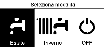
12 IT modalità di funzionamento caldaia Per selezionare la modalità di funzionamento della caldaia premere il tasto OK. Il display visualizza: - Programmato / Manuale - Estate / Inverno / Off - Menu completo Ruotare la manopola e selezionare: - Estate / Inverno / Off Premere il tasto OK. Ruotale la manopola e selezionare: - ( ) ESTATE produzione di acqua calda sanitaria, esclusione del riscaldamento. - ( ) INVERNO produzione di acqua calda sanitaria e riscaldamento. - ( ) OFF caldaia spenta, funzione antigelo attiva. Quando la funzione antigelo si attiva il display visualizza il simbolo:. Questa funzione è una protezione contro il congelamento delle tubature. Premere il tasto OK per confermare. Premere nuovamente il tasto OK per ritornare alla visualizzazione precedente. Selezione madalità inverno Ruotare la manopola e selezionare: - Programmato / Manuale Premere il tasto OK. Ruotale la manopola e selezionare: - ( ) PROGRAMMATO la caldaia funzionerà secondo la programmazione oraria impostata. - ( ) MANUALE la caldaia funzionerà in modalità manuale. Premere il tasto OK per confermare. Premere nuovamente il tasto OK per ritornare alla visualizzazione precedente. Selezione madalità manuale 12
13 regolazione temperatura ambiente IT In base alla modalità di funzionamento della caldaia (Programmato/Manuale) Vedi paragrafo modalità di funzionamento caldaia. Regolazione temperatura ambiente in modalità manuale Ruotare la manopola per impostare il valore di temperatura ambiente che si desidera. Il display visualizza il valore impostato. Premere il tasto OK per confermare. Il display ritorna alla visualizzazione predente. Regolazione temperatura ambiente in modalità programmazione oraria Durante il funzionamento della programmazione oraria è possibile modificare temporaneamente la temperatura ambiente impostata. Ruotare la manopola ed impostare il valore di temperatura ambiente che si desidera. Premere il tasto OK. Il display visualizza la temperatura impostata e l ora fino in cui si desidera mantenere la modifica. Ruotare la manopola per impostare l ora di fine modifica, premere il tasto OK per confermare. Il display visualizza il simbolo in corrispondenza del valore di temperatura desiderata per il periodo di modifica. Premere il tasto indietro per uscire dalla regolazione senza salvare la modifica. L interfaccia di sistema SENSYS manterrà il valore di temperatura fino al termine del tempo impostato, finito il quale tornerà alla temperatura ambiente preimpostata. Modifica temperatura ambiente Modifica temperatura ambiente in modalità programmazione oraria 13
14 IT impostazione acqua calda riscaldamento Per accedere alle impostazioni riscaldamento, premere il tasto OK. Ruotare la manopola e selezionare: - Menu completo Premere il tasto OK. Ruotale la manopola e selezionare: - Impostazione riscaldamento Premere il tasto OK. Per impostare la temperatura di mandata ruotale la manopola e selezionare: - Temperatura impostata riscaldamento Premere il tasto OK. Il display visualizza: - T impostata Zona 1 - T impostata Zona 2 - T impostata Zona 3 Ruotale la manopola e selezionare: - T impostata Zona 1 Premere il tasto OK. Ruotare la manopola ed impostare la temperatura di mandata della zona selezionata. Premere il tasto OK per confermare. Ripetere la procedura sopra descritta per impostare la temperatura di mandata nelle altre zone se presenti. Premere due volte il tasto indietro. Selezione Impostazioni riscaldamento Modifica temperatura acqua calda riscaldamento 14
15 programmazione oraria riscaldamento IT La programmazione oraria permette alla caldaia di riscaldare l ambiente secondo le proprie esigenze. Per impostare la programmazione oraria del riscaldamento premere il tasto OK. Ruotare la manopola e selezionare - Menu completo Premere il tasto OK. Ruotare la manopola e selezionare: - Impostazioni riscaldamento Premere il tasto OK. Il display visualizza: - Temperatura impostata riscaldamento - Programmazione oraria - Funzione vacanze - Funzione Auto Ruotare la manopola e selezionare: - Programmazione oraria Premere il tasto OK. Il display visualizza: - Programmazione libera - Programmazione guidata - Programmi pre-impostati - Programmazione/manuale Ruotare la manopola e selezionare: - PROGRAMMAZIONE LIBERA Premere il tasto OK. Il display visualizza: - Tutte le zone - Zona 1 - Zona 2 - Zona 3 Ruotare la manopola e selezionare la zona in cui si desidera effettuare la programmazione oraria: Premere il tasto OK. Ruotare la manopola e seleziona - Imposta T Comfort Premere il tasto OK. Ruotare la manopola e modificare il valore di temperatura ambiente durante il periodo comfort (il display visualizza il valore lampeggiante della temperatura). Premere il tasto OK per confermare. Ruotare la manopola e selezionare - Imposta T Ridotta Premere il tasto OK. Ruotare la manopola e modificare il valore di temperatura ambiente durante il periodo ridotto (il display visualizza il valore lampeggiante della temperatura). Premere il tasto OK per confermare. Ruotare la manopola e selezionare - Imposta programmazione Premere il tasto OK. Ruotare la manopola e selezionare il giorno o i giorni della settimana che si desidera programmare. Ad ogni selezione del giorno premere il tasto OK per confermare. Il display visualizza i giorni selezionati per la programmazione con un riquadro. Ruotare la manopola e selezionare salva. Premere il tasto OK e ruotare la manopola ed impostare l inizio del periodo di riscaldamento corrispondente al valore lampeggiante. Premere il tasto OK per confermare. Premere il tasto OK e ruotare la manopola per impostare l ora di fine periodo comfort. Se si desidera aggiungere nuovi periodi ruotare la manopola e selezionare Aggiungi periodo, prmere il tasto OK. Ripetere la procedura sopra descritta per impostare l inizio e la fine del periodo di comfort aggiunti. Una volta conclusa la programmazione ruotare la manopola e selezionare Salva. Premere il tasto OK per comfermare. 15
16 IT programmazione oraria riscaldamento Ruotare la manopola e selezionare: - Giorni rimanenti nell eventualità di giorni non ancora programmati e ripetere le operazioni precedentemente descritte Ruotare la manopola e selezionare: - Modifica per modificare eventuali periodo precedentemente programmati Ruotare la manopola e selezionare: - Esci per uscire dalla impostazione programmazione oraria. Premere il tasto OK per confermare. Il display ritorna alla visualizzazione predente. Premere il tasto indietro per ritornare alle visualizzazione della chermata principale. Per facilitare le operazioni di impostazione della programmazione oraria, è possibile eseguire la configurazione tramite: - Programmazione guidata - Programmi pre-impostati. Ruotare la manopola e selezionare: Selezione giorni programmazione oraria riscaldamento - PROGRAMMAZIONE GUIDATA Premere il tasto OK. Ruotare la manopola e selezionare la zona in cui si desidera effettuare la programmazione oraria. Premere il tasto OK. Ruotare la manopola e selezionare: - Imposta programmazione Premere il tasto OK. Ora seguire passo passo le indicazioni che vengono di volta in volta visualizzate a display. Imposta periodi comfort programmazione oraria riscaldamento 16
17 programmazione oraria riscaldamento IT - PROGRAMMI PRE-IMPOSTATI Premere il tasto OK. Ruotare la manopola e selezionare la zona in cui si desidera effettuare la programmazione oraria. Premere il tasto OK. Ruotare la manopola e selezionare - Imposta programmazione Premere il tasto OK. Ruotare la manopola e selezionare tra: - Programma famiglia - Programma no pranzo - Programma mezzogiorno - Sempre attivo Premere il tasto OK per comfermare. Ruotare la manopola per scorrere i giorni e l ora di inizio e di fine programma riscaldamento. Ruotare la manopola e selezionare salva premere il tasto OK. Premere il tasto indietro per ritornare alle visualizzazione precedente. Selezione programma mezzogiorno - PROGRAMMATO/MANUALE (questa modalità permette di selezionare la gestione del riscaldamento delle zone, tra programmato o manuale) Premere il tasto OK. Ruotare la manopola e selezionare la zona in cui effettuare l impostazione. Scelegliere tra la modalità programmazione oraria o manuale. Premere il tasto OK. Premere il tasto indietro per ritornare alle visualizzazione precedente Per regolare la temperatura ambiente è sufficiente ruotare la manopola. Selezione modalità funzionamento della zona 2 17
18 IT funzionamento modalità manuale riscaldamento La modalità manuale, disattiva la programmazione oraria di riscaldamento. Il funzionamento manuale, permette di mantenere il riscaldmanto in continuo. Per selezionare il funzionamento della caldaia in modalità manuale premere il tasto OK per accedere al Menu. Ruotare la manopola e selezionare: - Programmato / Manuale Premere il tasto OK. Ruotare la manopola e selezionare: - Manuale Ruotare la manopola per selezionare la modalità Manuale, premere il tasto OK. Premere nuovamente il tasto OK per salvare le impostazioni. Il display ritorna alla visualizzazione predente. Premere il tasto indietro fino alla visualizzazione della schermata principale. Selezione madalità manuale 18
19 impostazione acqua calda sanitaria IT Per accedere alle impostazioni acqua calda sanitaria, premere il tasto OK. Ruotare la manopola e selezionare: - Menu completo Premere il tasto OK. Ruotale la manopola e selezionare: - Impostazione acqua calda Premere il tasto OK. Ruotale la manopola e selezionare: - Temperatura impostata acqua calda Premere due volte il tasto OK. Ruotare la manopola ed impostare la temperatura desiderata dell acqua calda sanitaria. Premere il tasto OK per confermare. Premere il tasto indietro per ritornare alla visualizzazione precedente. La funzione comfort consente di ridurre il tempo di attesa quando si attiva la richiesta di acqua calda sanitaria. Selezione impostazione acqua calda Ruotale la manopola e selezionare: - Comfort Premere il tasto OK. Ruotare la manopola e selezionare: - Disabilitata - Temporizzata (permette di mantenere caldo lo scambiatore secondario durante i periodi di inattività della caldaia, aumentando così il benessere) - Sempre attiva Selezione modalità Comfort temporizzata 19
20 IT programmazione oraria acqua calda sanitaria Per impostare la programmazione oraria acqua calda sanitaria premere il tasto OK. Ruotare la manopola e selezionare - Menu completo Premere il tasto OK. Ruotare la manopola e selezionare - Impostazione acqua calda Premere il tasto OK. Ruotale la manopola e selezionare. - Programmazione oraria Premere il tasto OK. Ruotale la manopola per selezionare: - Programmazione libera - Programmi pre-impostati Ruotale la manopola per selezionare: - Programmazione libera Premere il tasto OK. Ruotare la manopola e selezionare: - Programma acqua calda - Timer ausiliario (Modulo per la produzione istantanea di acqua calda, Pompa ricircolo sanitario, Elettrosolare) In entrambi i casi ruotare la manopola ed impostare la temperatura comfort e ridotta, premere il tasto OK per confermare. Ruotale la manopola per selezionare: - Imposta programmazione Premere il tasto OK. Per impostare la programmazione seguire la procedura descritta nel capitolo programmazione oraria riscaldamento. Ruotale la manopola per selezionare: - Programmi pre-impostati Premere il tasto OK. Ruotare la manopola e selezionare: - Programmazione acqua calda - Timer ausiliario (Modulo per la produzione istantanea di acqua calda, Pompa ricircolo sanitario, Elettrosolare) In entrambi i casi ruotare la manopola ed impostare la temperatura comfort e ridotta, premere il tasto OK per confermare. Ruotale la manopola per selezionare: - Imposta programmazione Premere il tasto OK. Per impostare la programmazione seguire la procedura descritta nel capitolo programmazione oraria riscaldamento paragrafo, programmi pre-impostati: - Programma famiglia - Programma no pranzo - Programma mezzogiorno - Sempre attivo. Premere il tasto OK per comfermare la scelta e premere il tasto indietro per ritornare alle visualizzazione precedente. (SOLO PER CALDAIE SYSTEM) La funzione COMFORT consente di ridurre il tempo di attesa quando si attiva la richiesta di acqua calda sanitaria. Per accedere alle impostazioni acqua calda sanitaria, premere il tasto OK. Ruotare la manopola e selezionare: - Menu completo Premere il tasto OK. Ruotale la manopola e selezionare: - Impostazione acqua calda Premere il tasto OK. Ruotale la manopola e selezionare: - Funzione Comfort Premere il tasto OK. Ruotare la manopola e selezionare: - Disabilitata - Temporizzata (secondo la programmazione oraria) - Sempre attiva 20
21 funzioni speciali IT Per impostare la programmazione di una delle funzione speciali premere il tasto OK. Ruotare la manopola e selezionare - Menu completo Premere il tasto OK. Ruotare la manopola e selezionare: - Impostazioni riscaldamento Premere il tasto OK. Ruotare la manopola e selezionare: - Funzione vacanze - Funzione Auto Premere il tasto OK per comfermare la scelta. La funzione vacanze disattiva il riscaldamento durante il periodo di vacanza. - FUNZIONE VACANZE Premere il tasto OK. Ruotare la manopola e selezionare: - ON (attiva la funzione) - OFF (disattiva la funzione) Premere il tasto OK. Se si seleziona ON, ruotare la manopola per impostare la data di rientro dalle vacanze. Questo permetterà all interfaccia di sistema, nella data prestabilita, di riprendere il funzionamento nella modalità precedentemente impostata. Premere il tasto OK per salvare le impostazioni, il display ritorna alla visualizzazione predente. Nella schermata fonti attive, quando la funzione vacanze è attiva, compare l icona. La funzione AUTO imposta automaticamente il regime di funzionamento della caldaia in base al tipo di installazione e alle condizioni ambientali. La termoregolazione di un edificio consiste nel mantenerne la temperatura interna costante al variare della temperatura esterna. - FUNZIONE AUTO Premere il tasto OK. Ruotare la manopola e selezionare: - ON (attiva la funzione) - OFF (disattiva la funzione) Premere il tasto OK per salvare le impostazioni, il display ritorna alla visualizzazione predente. Nel caso in cui la temperatura dell acqua calda riscaldamento non corrisponda a quella desiderata è possibile aumentarla o diminuirla tramite parametro temperatura imposta riscaldamento. Il display visualizza la barra di correzione. Premere il tasto indietro per ritornare alle visualizzazione della chermata principale. Nella schermata fonti attive, quando la funzione auto è attiva, compare l icona. 21
22 IT Solare & Bollitore (ove presente) In presenza di un impianto solare, è possibile visualizzare le prestazioni energetiche del sistema installato. Ruotare la manopola e selezionare - Menu completo Premere il tasto OK. Ruotare la manopola e selezionare - Prestazioni sistema Premere il tasto OK. Ruotare la manopola e selezionare: - Fonti attive - Produzionw kw/h - C02 risparmiata - Docce disponibili - Reset Report Premere il tasto OK per confermare la selezione. - Fonti attive Visualizza l energia prodotta dal pannello solare nell arco di tempo che va dalle 24h, una settimana o un anno. - Produzione kwh Visualizza l energia prodotta dal pannello solare nell arco di tempo che va dalle 24h, una settimana o un anno. - Risparmio CO2 Visualizza il risparmio di CO2 in Kg mettendo in relazione la distanza percorsa in auto - Docce disponibili Visualizza la percentuale di acqua calda disponibile nell accumulo e la quantità di docce effettuabili. - Reset Report Resetta tutti i report. E anche possibile visualizzare lnella schermata principale lo schema di impianto solare installato. Schermata fonti attive Schermata prdduzione kwh 22
23 installazione IT Posizionamento L apparecchio rileva la temperatura ambiente, quindi nella scelta della posizione di installazione vanno tenuti presenti alcuni accorgimenti. Posizionarlo lontano da fonti di calore (radiatori, raggi solari, caminetti, ecc.) e lontano da correnti d aria o aperture verso l esterno, le quali potrebbero influenzarne la rilevazione. Installarlo a circa 1,50 m di altezza dal pavimento. fig. 1 Attenzione L installazione deve essere eseguita da personale tecnico qualificato. Prima del montaggio togliere la tensione alla caldaia. fig. 2 Installazione a parete Il fissaggio al muro dell interfaccia di sustema Sensys deve essere effettuato prima del collegamento alla linea BUS. - prima di collegare i fili alla base dell interfaccia di sistema, far scorrere la linguetta di protezione del connettore e sollevarla (fig.1), - collegare la coppia di fili al connettore (come spiegato nella pagina seguente) e richiudere la linguetta di protezione (fig.2), - aprire i fori necessari per il fissaggio - fissare la base dell apparecchio alla scatola sulla parete, usando le viti fornite nel kit (fig.3), - posizionare l interfaccia di sistema sulla base, spingendola delicatamente verso il basso (fig.4). fig. 3 fig. 4 23
24 1 IT installazione Collegamento alla caldaia L invio, la ricezione e la decodifica dei segnali avviene tramite il protocollo BUS BridgeNet, che mette in comunicazione la caldaia e l interfaccia di sistema. NOTA: Nel collegamento tra sensore ambiente e caldaia, per evitare problemi di interferenze, utilizzare un cavo schermato o un doppino telefonico. - collegare una coppia di fili al connettore BUS sulla scheda caldaia - collegare la coppia di fili dal connettore BUS al morsetto dell interfaccia di sistema. INTERFACCIA DI SISTEMA BUS B T T B FLOOR BUS TA2 SE TNK SCHEDA CALDAIA T B FLOOR BUS TA2 SE TNK SOL TA1 1 CN1 CN19 N L 1 CN14 1 CN13 FLAME N L CN4 CN9 1 CN15 24
25 struttura menu area tecnica IT Lingua, data e ora (Seguire le indicazioni del display, premere OK ad ogni inserimento per memorizzare) Impostazione Rete BUS BridgeNet (lista variabile in base ai dispositivi connessi) Controllo remoto (locale) Controllo solare Caldaia Menu completo (nelle pagine seguenti sono elencati tutti i menu/parametri disponibili) Configurazione guidata (lista variabile in base ai dispositivi connessi) Controllo solare (seguire le indicazioni riportate nella documentazione solare) Caldaia Parametri Parametri Gas: Parametri regolazione: Visualizzazioni: Zone: Procedure Guidate Riempi impianto Disareazione impianto Analisi Fumi Modalità test Test circolatore Test valvola tre vie Test ventilatore Opzione Assistenza Abilitazione Avviso di manutenzione Reset Avviso di Manutenzione Mesi mancanti alla manutenzione Manutenzione (lista variabile in base ai dispositivi connessi) Controllo solare (seguire le indicazioni riportate nella documentazione solare) Caldaia Parametri Parametri Gas: Visualizzazioni: Cambio scheda caldaia: Errori Il display visualizza gli ultimi 10 errori con indicazione del codice, descrizione, data. Ruotare la manopola per scorrere gli errori 25
26 IT area tecnica Attenzione Per garantire la sicurezza e il corretto funzionamento dell interfaccia di sistema, la messa in funzione deve essere eseguita da un tecnico qualificato in possesso dei requisiti di legge. Procedura di accensione - Inserire l interfaccia di sistema nella slitta di connessione spingendolo delicatamente verso il basso, dopo una breve inizializzazione l interfaccia di sistema è connessa; - Il display visualizza Selezionare lingua. Ruotare la manopola e selezionare la lingua desiderata. Premere il tasto OK per confermare. - Il display visualizza la data e l ora. Tramite la manopola selezionare il giorno, premere il tasto OK, ruotare la manopola per impostare il giorno esatto, premere il tasto OK per confermare e passare alla selezione del mese e successivamente dell anno confermando sempre l impostazione con il tasto OK. Ruotale la manopola per selezionare l ora, premere il tasto OK, ruotare la manopola per impostare l ora esatta, premere il tasto OK per confermare e passare alla selezione ed impostazione dei minuti. Premere il tasto OK per confermare. Ruotare la manopola e selezionare ora legale, premere il tasto OK, selezionare auto o manuale, premere il tasto OK. Il display visualizza la schermata base. - Premere contemporaneamente i tasti indietro e OK fino alla visualizzazione sul display Inserimento codice. - Ruotare la manopola per inserire il codice tecnico (234), premere il tasto OK, il display visualizza AREA TECNICA: - Lingua, data e ora - Impostazione rete Bus BridgeNet - Menu completo - Configurazione guidata - Manutenzione - Errori Ruotare la manopola e selezionare: - IMPOSTAZIONI RETE BUS Bridgenet Il display visualizza l elenco dei dispositivi connessi nel sistema: - Controllo remoto (locale) - Controllo solare - Caldaia -... I dispositivi configurabili sono contrassegnati dal simbolo. Per impostare la zona corretta a cui è associata l interfaccia di sistema ruotare la manopola e selezionare: - Controllo remoto (locale) Premere il tasto OK per comfermare la scelta e premere il tasto indietro per ritornare alle visualizzazione precedente. Ruotare la manopola e selezionare: - MENU COMPLETO Premere il tasto OK. Ruotare la manopola e scorrere tra i menu da selezionare: 0 Rete 1 Ora-Data-Lingua 2 Parametri Caldaia 3 Solare 4 Parametri Zona 1 5 Parametri Zona 2 26
27 area tecnica IT 6 Parametri Zona 3 7 Test & Utilità 8 Parametri Assistenza 9 Parametri Ibrido 10 Altre Periferiche 11 Free (periferiche 2 strato) 12 Free (periferiche 2 strato) 13 Free (periferiche 2 strato) 14 Zona 4 15 Zona 5 16 Zone 6 Selezionare il menu interessato, premere il tasto OK. Ruotare la manolpola per impostare o visualizzare il valore. Premere il tasto OK per confermare. Premere il tasto indietro per ritornare alle visualizzazione precedente. Per facilitare le operazioni di impostazione dei parametri, senza accedere al Menu completo, è possibile eseguire la configurazione tramite il menu di accesso rapido Configurazione guidata. Ruotare la manopola e selezionare: - CONFIGURAZIONE GUIDATA Premere il tasto OK. Ruotare la manopola e selezionare uno tra i dispositivi visualizzati. - Controllo Solare (ove presente) (seguire le indicazioni riportate nella documentazione solare) - Caldaia Ruotare la manopola e selezionare: - Caldaia Premere il tasto OK. Ruotare la manopola e selezionare: - Parametri - Procedure guidate - Modalità test - Opzioni assistenza Ruotare la manopola e selezionare: - Parametri (permette la visualizzazione e l impostazione dei parametri essenziali per il corretto funzionamento della caldia) Premere il tasto OK. Ruotare la manopola e scorrere tra i parametri da impostare: - Parametri gas - Parametri regolazione - Visualizzazioni - Zone Premere il tasto OK per confermare. Premere il tasto indietro per ritornare alle visualizzazione precedente. Ruotare la manopola e selezionare: - Procedure guidate (Le procedure guidate sono un valido aiuto nella parametrizzazione della caldia. Ruotando la manopola si seleziona l elenco delle procedure che spiegano passo passo come effettuare una corretta configurazione) Premere il tasto OK. Ruotare la manopola e scorrere tra i parametri da impostare: - Riempimento impianto - Disareazione impianto - Analisi fumi Premere il tasto OK per confermare. Premere due il tasto indietro per ritornare alle visualizzazione precedente Ruotare la manopola e selezionare: - Modalità Test (Questa modalità permette di controllare il corretto funzionamento dei componenti in caldaia) Premere il tasto OK. Ruotare la manopola e selezionare il Test da effettuare: - Test circolatore 27
28 IT area tecnica - Test valvola tre vie - Test ventilatore Premere il tasto OK per confermare. Premere due il tasto indietro per ritornare alle visualizzazione precedente. Ruotare la manopola e selezionare: - Opzioni assistenza (Questa modalità permette di memorizzare i dati del centro assistenza e gli avvisi di manutenzione) Premere il tasto OK. Ruotare la manopola e scorrere tra i parametri da impostare: - Dati centro assistenza - Abilitazione avvisi di manutenzione - Reset avvisi di manutenzione - Mesi mancanti manutenzione Premere il tasto OK per confermare. Premere due il tasto indietro per ritornare alle visualizzazione precedente. Ruotare la manopola e selezionare: - MANUTENZIONE (Nel caso si renda necessario controllare o configurare alcuni parametri essenziali per il corretto funzionamento della caldaia) Premere il tasto OK. Ruotare la manopola e selezionare: - Controllo Solare (ove presente) (seguire le indicazioni riportate nella documentazione solare) - Caldaia - Visualizzazioni - Cambio scheda caldaia Premere il tasto OK per confermare. Premere due il tasto indietro per ritornare alle visualizzazione precedente. Ruotare la manopola e selezionare: - ERRORI Premere il tasto OK. Ruotare la manopola e selezionare: - Controllo Solare (ove presente) (seguire le indicazioni riportate nella documentazione solare) - Controllo multizona (ove presente) - Caldaia Premere il tasto OK. Ruotare la manopola e selezionare - Caldaia Premere il tasto OK. Ruotare la manopola per scorrere sul display gli ultimi 10 errori registrati. Ruotare la manopola e selezionare: - Caldaia Premere il tasto OK. Ruotare la manopola e selezionare: - Parametri Premere il tasto OK. Ruotare la manopola e scorrere tra i parametri: - Parametri gas 28
29 termoregolazione IT Per impostare i parametri di termoregolazione premere contemporaneamenti i tasti indietro e OK fino alla visualizzazione sul display Inserimento codice. Ruotare la manopola per inserire il codice tecnio (234), premere il tasto OK, il display visualizza Area tecnica. Ruotare la manopola e selezionare Menu completo. Premere il tasto OK. Ruotare la manopola e selezionare: 4 Parametri Zona 1 Premere il tasto OK. Ruotare la manopola e selezionare: 4.2 Impostazione Zona 1 Premere il tasto OK. Ruotare la manopola e selezionare: Range T Z1 Premere il tasto OK. Ruotare la manopola e selezionare il range di temperatura: 0 bassa temperatura 1 alta temperatura Premere il tasto OK. per confermare. Ruotare la manopola e selezionare: Selezione tipologia premere il tasto OK Ruotare la manopola ed impostare la tipologia di termoregolazione installata: - 0 Temperatura fissa di mandata - 1 Dispositivi ON/OFF - 2 Solo Sonda Ambiente - 3 Solo Sonda Esterna - 4 Sonda Ambiente + Sonda Esterna premere il tasto OK Ruotare la manopola e selezionare: Curva Termoregolazione premere il tasto OK Ruotare la manopola ed impostare la curva a seconda del tipo di impianto di riscaldamento e premere il tasto OK. - impianto a bassa temperatura (pannelli a pavimento) curva da 0,2 a 0,8 - impianto ad alta temperatura (radiatori) curva da 1,0 a 3,5 La verifica dell idoneità della curva scelta richiede un tempo lungo nel quale potrebbero essere necessari alcuni aggiustamenti. Al diminuire della temperatura esterna (inverno) si possono verificare tre condizioni: 1. la temperatura ambiente diminuisce, questo indica che bisogna impostare un curva con maggiore pendenza 2. la temperatura ambiente aumenta questo indica che bisogna impostare una curva con minore pendenza 3. la temperatura ambiente rimane costante, questo indica che la curva impostata ha la pendenza giusta Trovata la curva che mantiente costante la temperatura ambiente bisogna verificare il valore della stessa Ruotare la manopola e selezionare: Spostamento Parallelo premere il tasto OK. Ruotare la manopola ed impostare il valore più idoneo. Premere il tasto OK per confermare. NOTA: Se la temperatura ambiente risulta maggiore del valore desiderato bisogna traslare parallelamente la curva verso il basso. Se invece la temperatura ambiente risulta minore bisogna traslarla parallelamente verso l alto. Se la temperatura ambiente corrisponde a quella desiderata la curva è quella esatta. Nella rappresentazione grafica sotto ri- 29
30 IT termoregolazione portata, le curve sono divise in due gruppi: - impianti a bassa temperatura - impianti ad alta temperatura La divisione dei due gruppi è data dal differente punto di origine delle curve che per l alta temperatura è di + 10 C, correzione che abitualmente viene data alla temperatura di mandata di questo tipo di impianti, nella regolazione climatica. golabile tra 20 (massima influenza) e 0 (influenza eslcusa). In questo modo è possibile regolare il contributo della temperatra ambiente nel calcolo dellla temperatura di mandata. Ruotare la manopola e selezionare: Temperatura massima mandata premere il tasto OK. Ruotare la manopola ed impostare il valore più idoneo e premere il tasto OK Ruotare la manopola e selezionare: Temperatura minima mandata premere il tasto OK Ruotare la manopola ed impostare il valore più idoneo e premere il tasto OK. Ripetere le operazioni descritte per impostare i valori delle zone 2 e 3 selezionando il menu 5 e 6. C Ruotare la manopola e selezionare: Influenza Ambiente Proporzionale premere il tasto OK. Ruotare la manopola ed impostare il valore più idoneo e premere il tasto OK. L influenza della sonda ambiente è retemperatura di mandata all impianto C valore di consegna temperatura ambiente bassa tempertaura alta tempertaura C temperatura esterna grafico famiglia curve 30
31 menu - impostazioni IT MENU SOTTO-MENU PARAMETRO DESCRIZIONE RANGE NOTE 0 RETE 0 2 Rete BUS Rete BUS attuale Caldaia Interfaccia di sistema Controllo solare Multi funzione Energy Manager Energy Manager ibrido Gestore cascate Pompa di calore Sensore ambiente Controllo multi zona Modem remoto Clip multi funzione Fresh Water Station Controllo piscine Interfaccia utente Controllo multi stanza 0 3 Interfaccia di sistema Numero zona Correzione temperatura ambiente Nessuna zona selezionata Zona selezionata Versione SW interfaccia 0 4 Display caldaia Zona da impostare da display Temporizzazione backlight Disattiva tasto di termoregolazione 2 PARAMETRI CALDAIA 2 0 Impostazioni Generali Impostazioni temperatura sanitario 2 1 Parametri generici 31
32 IT menu - impostazioni MENU SOTTO-MENU PARAMETRO DESCRIZIONE RANGE NOTE Parametri generici caldaia 2 2 Impostazioni Livello Lenta Accensione Alto rapporto modulazione ON - OFF Modulazione ventilatore Termostato Pavimento o TA Termoregolazione Ritardo Partenza Riscaldamento Configurazione caldaie convenzionali Caldaia Ibrida Versione Caldaia Potenza nominale caldaia 0. Esclusa 1. Attiva 0. Termostato Pavimento 1. Termostato Ambiente2 0. Assente 1. Presente 0. Disabilitata sec sec sec 0. Mono camera aperta 1. Mono camera aperta VMC 2. Mono camera stagna ventilatore fisso 3. Mono camera stagna ventilatore modulante 4. Bitermica camera aperta 5. Bitermica camera stagna 0. Esclusa 1. Attiva 0. Mista Istantanea 1. Accumulo Ext con Sonda NTC 2. Accumulo Ext con Termostato 3. Microaccumulo 4. Accumulo a Stratificazione 6. Storage 32
33 menu - impostazioni IT MENU SOTTO-MENU PARAMETRO DESCRIZIONE RANGE NOTE 2 3 Riscaldamento Livello Max Pot Riscaldamento Assoluta Livello Max Pot Riscaldalmento Regolabile Percentuale Potenza Max Sanitario Percentuale Potenza min Percentuale Potenza Max Riscaldamento Tipo Ritardo di Accensione Riscaldamento Impostazione Ritardo Accensione 0. Manuale 1. Automatico Postcircolazione Riscaldamento Funzionamento Circolatore 0. Bassa velocità 1. Alta velocità 2. Modulante DeltaT Modulazione Circolatore 2 4 Riscaldamento Pressione Minima Pressione Allerta Pressione Riempimento Post ventilazione Riscaldamento OFF - ON Tempo Incremento Temperatura Risc Max PWM pompa Min PWM pompa Dispositivo Rilevazione Pressione Risc 0. Solo Sonde T 1. Pressostato di Minima 2. Sensore Pressione Abilitazine Riempimento Semiautomatico Correzione Temperatura esterna 33
34 IT menu - impostazioni MENU SOTTO-MENU PARAMETRO DESCRIZIONE RANGE NOTE 2 5 Sanitario Funzione Comfort 0. Disabilitata 1. Temporizzata 2. Sempre Attiva Tempo Anticiclaggio Comfort Ritardo Partenza Sanitario Logica Spegn Bruciatore Sanitario 0. Anticalcare 1. Set-point più 4 C Post-raffreddamento Sanitario ON - OFF Ritardo San- > Risc Celectic ON - OFF Funzione Anti-legionella ON - OFF Frequenza antilegionella Temperatura obbiettivo antilegionella 2 6 Forzamenti manuali caldaia Attivazione modo manuale 0. Modo normale 1. Modo manuale Forzamento pompa caldaia ON - OFF Forzamento ventilatore ON - OFF Forzamento valvola deviatrice Sanitario Riscaldamento Forzamento pompa sanitaria ON - OFF Forzamento modulo Aerotech ON - OFF 2 7 Cicli di verifica Spazzacamino ON - OFF Ciclo Disareazione ON - OFF 2 8 Reset menu 34
35 menu - impostazioni IT MENU SOTTO-MENU PARAMETRO DESCRIZIONE RANGE NOTE Ripristino Impost di Fabbrica OK = Sì, esc = No 3 SOLARE 3 0 Impostaz Generali Impostazione Temperatura Accumulo Impostazione Temp. Ridotta Accumulo 3 1 Statistiche Solari Energia Solare Energia Solare Tempo Tot ON Pompa Solare Tempo Tot Sovratemperatura Coll Solare 3 2 Impostazioni Solari Funzione Anti Legionella ON - OFF Schema Idraulico Funzionamento resistenza elettrica DeltaT Collettore per Avvio Pompa 0. Non definito 1. Base mono serpentino 2. Base doppio serpentino 3. Elettrosolare 4. Integrazione riscaldamento 0. EDF 1. Temporizzata DeltaT Collettore per Stop Pompa Min T Collettore per Avvio Pompa Collectorkick ON - OFF Funzione Recooling ON - OFF Setpoint Accumulo con Gas Temperatura Antigelo Collettore 3 3 Impostazioni Solari 2 35
36 IT menu - impostazioni MENU SOTTO-MENU PARAMETRO DESCRIZIONE RANGE NOTE Impostazioni Portata Fluido Gruppo Ciroclazione Digitale ON - OFF Presenza sensore pressione ON - OFF Presenza Anodo Pro-Tech ON - OFF Funzione Uscita AUX 0. Richiesta integrazione 1. Allarme 2. Pompa de-stratificazione Delta T obbiettivo x modulazione Frequenza antilegionella Temperatura obbiettivo antilegionella Parametro generico solare Parametro generico solare 3 4 Modo Manuale Attivazione Modo Manuale ON - OFF Attiva Pompa Solare ON - OFF Attiva Valvola 3 vie ON - OFF Attiva Uscita AUX ON - OFF Attiva Uscita Out ON - OFF Controllo valvola Mix 0. ON 1. Aperto 2. Chiuso 3 5 Diagnostica Solare Temperatura Collettore Solare Sonda Bassa Bollitore Sonda Alta Bollitore Temperatura Ritorno Riscaldamento Sonda ingresso collettore 36
37 menu - impostazioni IT MENU SOTTO-MENU PARAMETRO DESCRIZIONE RANGE NOTE Sonda uscita collettore 3 6 Diagnostica Solare Portata Circuito Solare Pressione Circuito Solare Capacità Accumulo 0. Non definito l l l Numero Docce Disponibili % Riempimento Bollitore 3 8 Storico Errori Ultimi 10 Errori Reset Lista Errori Reset? OK=Si, esc=no 3 9 Reset Menu Ripristino Impostazioni Fabbrica 4 PARAMETRI ZONA Impostazione Temperature Temperatura Giorno Temperatura Notte Temperatura set Z Temperatura antigelo zona 4 1 Parametri generici Parametro generico zona Parametro generico zona Parametro generico zona 4 2 Impostaz Zona1 37
38 IT menu - impostazioni MENU SOTTO-MENU PARAMETRO DESCRIZIONE RANGE NOTE Range Temperatura Selezione Tipologia Termoregolazione Curva Termoregolazione 0. Bassa Temperatura 1. Alta Temperatura 0. Temperatura Fissa di Mandata 1. Dispositivi ON/OFF 2. Solo Sonda Ambiente 3. Solo Sonda Esterna 4. Sonda Ambiente + Sonda Esterna Spostamento Parallelo Influenza Ambiente Proporzionale Max T Min T Tipologia Circuito Riscaldamento 0. Termosifoni Veloci 1. Termosifoni Medi 2. Termosifoni Lenti 3. Impianto Pavimento Veloce 4. Impianto Pavimento Medio 5. Impianto Pavimento Lento 6. Controllo Ambiente solo Proporzionale Max azione Integrale su sensore ambiente HYD 4 3 Diagnostica Zona Temperatura Ambiente Temperatura Set ambiente Temperatura mandata Temperatura ritorno Stato Richiesta Calore Z1 ON - OFF Stato Pompa ON - OFF 4 4 Dispositivi Zona1 38
39 menu - impostazioni IT MENU SOTTO-MENU PARAMETRO DESCRIZIONE RANGE NOTE Zone pump modulation 0. Velocità fissa 1. Modulante su deltat 2. Modulante su pressione DeltaT obbiettivo per modulazione Velocità fissa pompa 5 PARAMETRI ZONA Imposta Temperature Temperatura Giorno Temperatura Notte Temperatura Zona Temperatura Antigelo zona 5 1 Parametri generici Parametro generico zona Parametro generico zona Parametro generico zona 5 2 Impostazioni Zona Range Temperatura Selezione Tipologia Termoregolazione Curva Termoregolazione 0. Bassa Temperatura 1. Alta Temperatura 0. Temperatura Fissa di Mandata 1. Dispositivi ON/OFF 2. Solo Sonda Ambiente 3. Solo Sonda Esterna 4. Sonda Ambiente + Sonda Esterna Spostamento Parallelo Influenza Ambiente Proporzionale Max T Min T 39
40 IT menu - impostazioni MENU SOTTO-MENU PARAMETRO DESCRIZIONE RANGE NOTE Tipologia Circuito Riscaldamento 0. Termosifoni Veloci 1. Termosifoni Medi 2. Termosifoni Lenti 3. Impianto Pavimento Veloce 4. Impianto Pavimento Medio 5. Impianto Pavimento Lento 6. Controllo Ambiente solo Proporzionale Max azione Integrale su sensore ambiente HYD 5 3 Diagnostica Zona Temperatura Ambiente Temperatura Set ambiente Temperatura mandata Temperatura ritorno Stato Richiesta Calore Z2 ON - OFF Stato Pompa ON - OFF 5 4 Dispositivi Zona Zone pump modulation 0. Velocità fissa 1. Modulante su delta T 2. Modulante su pressione DeltaT obbiettivo per modulazione Velocità fissa pompa 6 PARAMETRI ZONA Imposta Temperature Temperatura Giorno Temperatura Notte Temperatura Zona Temperatura Antigelo zona 6 1 Parametri generici 40
41 menu - impostazioni IT MENU SOTTO-MENU PARAMETRO DESCRIZIONE RANGE NOTE Parametro generico zona Parametro generico zona Parametro generico zona Impostazioni Zona Range Temperatura Selezione Tipologia Termoregolazione Curva Termoregolazione 0. Bassa Temperatura 1. Alta Temperatura 0. Temperatura Fissa di Mandata 1. Dispositivi ON/OFF 2. Solo Sonda Ambiente 3. Solo Sonda Esterna 4. Sonda Ambiente + Sonda Esterna Spostamento Parallelo 6 2 Impostazioni Zona Max T Min T Tipologia Circuito Riscaldamento 0. Termosifoni Veloci 1. Termosifoni Medi 2. Termosifoni Lenti 3. Impianto Pavimento Veloce 4. Impianto Pavimento Medio 5. Impianto Pavimento Lento 6. Controllo Ambiente solo Proporzionale Max azione Integrale su sensore ambiente HYD Influenza Ambiente Proporzionale Max T Min T 41
42 IT menu - impostazioni MENU SOTTO-MENU PARAMETRO DESCRIZIONE RANGE NOTE Tipologia Circuito Riscaldamento Termosifoni Veloci Termosifoni Medi Termosifoni Lenti Impianto Pavimento Veloce Impianto Pavimento Medio Impianto Pavimento Lento Controllo Ambiente solo Proporzionale Max azione Integrale su sensore ambiente 6 3 Diagnostica Zona Temperatura Ambiente Temperatura Set ambiente Temperatura mandata Temperatura ritorno Stato Richiesta Calore Z3 ON - OFF Stato Pompa ON - OFF 6 4 Dispositivi Zona Zone pump modulation 0. Velocità fissa 1. Modulante su delta T 2. Modulante su pressione DeltaT obbiettivo per modulazione Velocità fissa pompa 7 MODULO DI ZONA 7 1 Modo Manuale Attivazione modo manuale ON - OFF Controllo pompa Z1 ON - OFF Controllo pompa Z2 ON - OFF Controllo pompa Z3 ON - OFF 42
43 menu - impostazioni IT MENU SOTTO-MENU PARAMETRO DESCRIZIONE RANGE NOTE Controllo valvola mix Z Controllo valvola mix Z3 7 2 Modulo di zona Schema idraulico Correzione T Mandata Funzione uscita AUX Correzione Temperatura Esterna 0. OFF 1. Aperto 2. Chiuso 0. OFF 1. Aperto 2. Chiuso 0. Non definito 1. MCD 2. MGM II 3. MGM III 4. MGZ I 5. MGZ II 6. MGZ III 0. Richiesta Calore 1. Pompa esterna 2. Allarme 7 3 Parametri generici Parametro generico modulo zona Parametro generico modulo zona Parametro generico modulo zona 7 4 Modo Manuale Attivazione modo manuale ON - OFF Controllo pompa Z1 ON - OFF Controllo pompa Z2 ON - OFF Controllo pompa Z3 ON - OFF Controllo valvola mix Z2 0. OFF 1. Aperto 2. Chiuso 43
44 IT menu - impostazioni MENU SOTTO-MENU PARAMETRO DESCRIZIONE RANGE NOTE Controllo valvola mix Z3 0. OFF 1. Aperto 2. Chiuso 7 5 Modulo di zona Schema idraulico 0. Non definito 1. MCD 2. MGM II 3. MGM III 4. MGZ I 5. MGZ II 6. MGZ III Correzione T Mandata Funzione uscita AUX 0. Richiesta Calore 1. Pompa esterna 2. Allarme Correzione Temperatura Esterna 7 6 Parametri generici Parametro generico zona Parametro generico zona Parametro generico zona 7 8 Storico errori Ultimi 10 errori Reset Lista Errori Resettare? OK=Sì, esc=no Ultimi 10 errori Reset Lista Errori 2 Resettare? OK=Sì, esc=no 7 9 Reset Menu Ripristino Impost di Fabbrica Resettare? OK=Sì, esc=no Ripristino Impost di Fabbrica 2 Resettare? OK=Sì, esc=no 44
45 menu - impostazioni IT MENU SOTTO-MENU PARAMETRO DESCRIZIONE RANGE NOTE 8 PARAMETRI ASSISTENZA 8 1 Statistiche Ore Bruciatore ON Risc (h x10) Ore Bruciatore ON San (h x10) Nr Distacchi Fiamma (n x10) Nr Cicli Accensione (n x10) Durata Media Richieste Calore Numero Cicli Riempimento 8 2 Caldaia Livello Modulazione Bruciatore Stato Ventilatore ON - OFF Velocità Ventilatore x100rpm Livello Velocità Pompa Posizione Valvola Deviatrice Portata Sanitario l/min Stato Pressostato Fumi % Modulazione pompa 0. OFF 1. Velocità bassa 2. Velocità alta 0. Sanitario 1. Riscaldamento 0. Aperto 1. Chiuso Potenza istantanea 8 3 Temperature Caldaia Temp Impostata Riscaldamento Temperatura Mandata Riscaldamento Temperatura Ritorno Riscaldamento Temperatura Misurata Sanitario 45
46 IT menu - impostazioni MENU SOTTO-MENU PARAMETRO DESCRIZIONE RANGE NOTE Temperatura Fumi Temperatura esterna 8 4 Solare & Bollitore Temperatura Misurata Accumulo Temperatura Collettore Solare Temperatura Ingresso Sanitario Sonda Bollitore Bassa Temperatura Set Bollitore Stratificazione 8 5 Service Mesi Mancanti Alla Manutenzione Abilitazione Avvisi Manutenzione ON - OFF Cancellazione Avvisi Manutenzione Cancellare? OK=Sì, esc=no Stato Intasamento Scambiatore Sanitario 0. Scambiatore Sanitario OK 1. Parzialmente Intasato 2. Molto intasato Da sostituire Versione HW Scheda Versione SW Scheda Stato Carica Vaso Espansione 8 6 Storico errori 0. Da Ricaricare 1. OK Ultimi 10 errori Reset Lista Errori Reset? OK=Sì, esc=no 8 7 Parametri generici Parametro generico caldaia zona Parametro generico caldaia zona Parametro generico caldaia zona 46
47 menu - impostazioni IT MENU SOTTO-MENU PARAMETRO DESCRIZIONE RANGE NOTE 9 PARAMETRI IBRIDO 9 0 User Parameters Eco / Comfort Forzamento manuale PdC/Caldaia 9 1 Statistiche Energy Manager PdC ore di funzionamento (h/10) PdC n. Cicli Accensione (n/10) PdC n. Cicli sbrinamento (n/10) PdC+Caldaia ore di funzionamento (h/10) 9 2 Costi dell'energia Temp Est. x Disabilitazione Caldaia Temp Est. x Disabilitazione PdC OFFSET Max Temp Impostabile PdC Limitazione Freq compressore HP Min Rapporto Costo Elettricità/Gas Max Rapporto Costo Elettricità/Gas Rapporto Energia Primaria /Energia Elec Logica Energy Manager Temp. ambiente set-mis x ON caldaia 9 3 Costi dell'energia 2 0. Eco Plus 1. Eco 2. Medio 3. Comfort 4. Comfort Plus 0. Auto 1. Solo Caldaia 2. Solo PdC 0. Massimo Risparmio 1. Massima Ecologia HYB HYB Modo Notturno PdC ON - OFF 47
48 IT menu - impostazioni MENU SOTTO-MENU PARAMETRO DESCRIZIONE RANGE NOTE Ora Inizio Modo Notturno PdC [hh:mm] Ora Fine Modo Notturno PdC [hh:mm] Costo kwh gas (PCS) Costo kwh elettricità Costo kwh elettricità tariffa ridotta Parametro generico energy manager Parametro generico energy manager Parametro generico energy manager 9 4 Temperature PdC Temperatura esterna Temperatura mandata PdC Temperatura ritorno PdC Temperatura evaporatore PdC Temperatura gas PdC PdC Temperatura Condensatore (ICT) 9 5 Stato PdC Frequenza misurata compressore Modulazione richiesta al compressore Modulazione calcolata caldaia Modo di funzionamento PdC 0. Stand-by 1. Non presente 2. Modo caldo 3. Sbrinamento PdC Errore presente Scheda ODU PdC Errore presente Scheda HYDI PdC Codice Errore Scheda ODU 48
49 menu - impostazioni IT MENU SOTTO-MENU PARAMETRO DESCRIZIONE RANGE NOTE PdC Codice Errore Scheda HYDI Stato Energy Manager 9 6 Info Energy Manager Costo attuale KWh da PdC Costo attuale KWh da Caldaia Costo stimato KWh da PdC Costo stimato KWh da Caldaia Temperatura Mandata Riscaldamento Temperatura Ritorno Riscaldamento Stato Pompa Riscaldamento 9 7 Cicli di verifica HP 0. Spenta 1. Accesa Forza modo deice PdC ON - OFF Forza compressore PdC freq fissa ON - OFF 9 8 Storico errori Ultimi 10 errori Reset Lista Errori Reset? OK=Sì, esc=no 9 9 Reset Menu Ripristino Impost di Fabbrica Reset? OK=Sì, esc=no 10 FRESH WATER STATION 10 0 Parametri utente Impostazione Temperatura Accumulo 10 1 Modo Manuale Attivazione modo manuale ON - OFF Attiva pompa solare ON - OFF 49
50 IT menu - impostazioni MENU SOTTO-MENU PARAMETRO DESCRIZIONE RANGE NOTE Attiva valvola 3 vie ON - OFF Attiva uscita AUX ON - OFF Controllo valvola mix 0. OFF 1. Aperto 2. Chiuso 10 2 Parametri FWS Schema Idraulico Tipo pompa circolazione sanitario Parametro generico FWS 0. Non definito 1. Senza pompa ricircolo sanit 2. Con pompa ricircolo sanit 0. Temporizzata 1. Dopo prelievo Parametro generico FWS Parametro generico FWS 10 3 Diagnostica FWS Temperatura uscita sanitario Temperatura ingresso Sanitario Temperatura Ritorno Riscaldamento Temperatura Mandata Riscaldamento Portata Sanitario Sonda Bollitore Bassa Consumo sanitario totale Tempo Totale ON Pompa FWS 11 SCHEDINO MULTIFUNZIONE 11 0 Generale 50
51 menu - impostazioni IT MENU SOTTO-MENU PARAMETRO DESCRIZIONE RANGE NOTE Selezione funzione 0. Non definito 1. 3 zone dirette 2. Notifica errori e reset 3. Termostato differenziale 4. Termostato 5. Uscita temporizzata Attivazione modo manuale ON - OFF Controllo OUT1 ON - OFF Controllo OUT2 ON - OFF Controllo OUT3 ON - OFF 11 1 Diagnostica Temperatura IN Temperatura IN Temperatura IN Stato OUT Stato OUT Stato OUT Termostato differenziale Differenziale accensione termostato Differenziale spegnimento termostato Massima temperatura IN Massima temperatura IN Minima temperatura IN Termostato Temperatura impostata termostato Isteresi termostato 11 4 Parametri generici 51
52 IT menu - impostazioni MENU SOTTO-MENU PARAMETRO DESCRIZIONE RANGE NOTE Parametro generico multifunzionale Parametro generico multifunzionale Parametro generico multifunzionale Parametro generico multifunzionale Parametro generico multifunzionale Parametro generico multifunzionale Parametro generico multifunzionale 14 PARAMETRI ZONA Impostazione Temperature Temperatura Giorno Temperatura Notte Temperatura set Z Parametri generici Parametro generico zona Parametro generico zona 14 2 Impostazione Zona Range Temperatura Zona Selezione tipologia termoregolazione Curva Termoregolazione 0. Bassa Temperatura 1. Alta Temperatura 0. Temperatura Fissa di Mandata 1. Dispositivi ON/OFF 2. Solo Sonda Ambiente 3. Solo Sonda Esterna 4. Sonda Ambiente + Sonda Esterna Spostamento Parallelo Influenza Ambiente Proporzionale Max Temperatura 52
53 menu - impostazioni IT MENU SOTTO-MENU PARAMETRO DESCRIZIONE RANGE NOTE Min Temperatura Tipologia Circuito Riscaldamento Termosifoni Veloci Termosifoni Medi Termosifoni Lenti Impianto Pavimento Veloce Impianto Pavimento Medio Impianto Pavimento Lento Controllo Ambiente solo Proporzionale Max azione Integrale su sensore ambiente 14 3 Diagnostica Zona Temperatura Ambiente Temperatura Set ambiente Temperatura mandata Temperatura ritorno Stato Richiesta Calore Z 4 ON - OFF Stato Pompa ON - OFF 14 4 Dispositivi Zona Modulazione pompa zona 0. Velocità fissa 1. Modulante su delta T 2. Modulante su pressione DeltaT obbiettivo per modulazione Velocità fissa pompa 15 PARAMETRI ZONA Impostazione Temperature Temperatura Giorno Temperatura Notte Temperatura set Z Temperatura antigelo zona 53
54 IT menu - impostazioni MENU SOTTO-MENU PARAMETRO DESCRIZIONE RANGE NOTE 15 1 Parametri generici Parametro generico zona Parametro generico zona 15 2 Impostazione Zona Range Temperatura Zona Selezione tipologia termoregolazione Curva Termoregolazione 0. Bassa Temperatura 1. Alta Temperatura 0. Temperatura Fissa di Mandata 1. Dispositivi ON/OFF 2. Solo Sonda Ambiente 3. Solo Sonda Esterna 4. Sonda Ambiente + Sonda Esterna Spostamento Parallelo Influenza Ambiente Proporzionale Max Temperatura Min Temperatura Tipologia Circuito Riscaldamento Termosifoni Veloci Termosifoni Medi Termosifoni Lenti Impianto Pavimento Veloce Impianto Pavimento Medio Impianto Pavimento Lento Controllo Ambiente solo Proporzionale Max azione Integrale su sensore ambiente 15 3 Diagnostica Zona Temperatura Ambiente Temperatura Set ambiente Temperatura mandata Temperatura ritorno 54
55 menu - impostazioni IT MENU SOTTO-MENU PARAMETRO DESCRIZIONE RANGE NOTE Stato Richiesta Calore Z5 ON - OFF Stato Pompa ON - OFF 15 4 Dispositivi Zona Modulazione pompa zona 0. Velocità fissa 1. Modulante su delta T 2. Modulante su pressione DeltaT obbiettivo per modulazione Velocità fissa pompa 16 PARAMETRI ZONA Impostazione Temperature Temperatura Giorno Temperatura Notte Temperatura set Z Temperatura antigelo zona 16 1 Parametri generici Parametro generico zona Parametro generico zona Parametro generico zona 16 2 Impostazione Zona Range Temperatura Zona Selezione tipologia termoregolazione Curva Termoregolazione 0. Bassa Temperatura 1. Alta Temperatura 0. Temperatura Fissa di Mandata 1. Dispositivi ON/OFF 2. Solo Sonda Ambiente 3. Solo Sonda Esterna 4. Sonda Ambiente + Sonda Esterna Spostamento Parallelo 55
56 IT menu - impostazioni MENU SOTTO-MENU PARAMETRO DESCRIZIONE RANGE NOTE Influenza Ambiente Proporzionale Max Temperatura Min Temperatura Tipologia Circuito Riscaldamento Termosifoni Veloci Termosifoni Medi Termosifoni Lenti Impianto Pavimento Veloce Impianto Pavimento Medio Impianto Pavimento Lento Controllo Ambiente solo Proporzionale Max azione Integrale su sensore ambiente 16 3 Diagnostica Zona Temperatura Ambiente Temperatura Set ambiente Temperatura mandata Temperatura ritorno Stato Richiesta Calore Z3 ON - OFF Stato Pompa ON - OFF 16 4 Dispositivi Zona Modulazione pompa zona 0. Velocità fissa 1. Modulante su delta T 2. Modulante su pressione DeltaT obbiettivo per modulazione Velocità fissa pompa 56
57 tabella codici errori IT ERRORE DESCRIZIONE 1 01 Sovratemperatura 1 02 Errore Sensore Pressione Circolazione Insufficiente Riempi Impianto 1 11 Premi Puls Riempimento 1 09 Alta Press Acqua 1 10 Sonda RISC Difettosa 1 12 Sonda Rit Difettosa 1 14 Sonda Esterna Difettosa 1 16 Termost pav Aperto 1 18 Problema Sonde Primario Errore caldaia P1 1 P2 Circolazione Insufficiente 1 P3 1 P4 Riempi Impianto 1 P4 Premi Puls Riempimento 1 P5 Riemp Incompleto 1 P6 Riemp Incompleto 1 P7 Troppi Riempimenti 1 P8 Troppi Riempimenti 2 01 Sonda Sanit Difettosa 2 02 Sonda Acc Bassa Difettosa 2 03 Sonda Acc Difettosa 2 04 Sonda Coll Solare Difettosa ERRORE DESCRIZIONE 2 05 Sonda Ing San Difettosa 2 07 Coll Solare Max Temp 2 08 Coll Solare Antigelo 2 09 Sovratemp Accumulo 2 10 Sonda acc alta difettosa 2 11 Sonda ritorno risc solare difettosa 2 12 Sonda ingresso collettore difettosa 2 13 Sonda uscita collettore difettosa 2 14 Schema idraulico solare non definito 2 15 Err sens pressione solare 2 16 Riempi impianto solare 2 17 Errore anodo 2 P1 Riempi impianto solare 2 P2 Antilegionella non completata 2 40 Errore solare 2 41 Errore solare 2 50 Schema idraulico non definito 2 51 Sonda uscita sanit FWS difettosa 2 52 Sonda ingresso risc FWS difettosa 2 53 Sonda uscita risc FWS difettosa 2 54 Sonda ingresso sanit FWS difettosa 2 70 Errore FWS 2 71 Errore FWS 3 01 Display EEPR err 3 02 GP-GIU comm err 3 03 Errore Scheda 3 04 Troppi sblocchi 3 05 Errore Scheda 3 06 Errore Scheda 3 07 Errore Scheda 3 P9 Manutenzione Programmata Chiama Assistenza 57
58 IT tabella codici errori ERRORE DESCRIZIONE 3 08 Errore configuraz ATM 3 09 Errore relè gas 3 11 Errore caldaia 3 12 Errore caldaia 4 01 Mdm-Bus Com err 4 02 GPRS mdm error 4 03 Sim Card error 4 04 Mdm-PCB Com err 4 05 Mdm In1 error 4 06 Mdm In2 error 4 11 Non disponibile Sonda Amb Z Non disponibile Sonda Amb Z Non disponibile Sonda Amb Z Non disponibile Sonda Amb Z Non disponibile Sonda Amb Z Non disponibile Sonda Amb Z Sovraccarico alimentazione bus (*) 4 21 Errore caldaia 4 22 Errore caldaia 5 01 Mancanza Fiamma 5 02 Fiamma senza Gas 5 04 Distacco fiamma 5 P1 1 Accens Fallita 5 P2 2 Accens Fallita 5 P3 Distacco fiamma 5 P4 Distacco fiamma 5 10 Errore caldaia Err Sonda fumi Bassi giri Vent 6 05 Sonda Fumi Difettosa ERRORE DESCRIZIONE 6 07 Pressost ON Vent OFF 6 08 Pressost OFF Vent ON 6 09 Sovratemp Fumi 6 10 Sonda Scamb Aperta 6 12 Err Ventilatore 6 P1 Ritardo Press Fumi 6 P2 Apertura Press Fumi 6 P4 Bassi giri Vent 6 20 Errore caldaia 6 21 Errore caldaia 7 01 Sonda Mandata Z1 Difettosa 7 02 Sonda Mandata Z2 Difettosa 7 03 Sonda Mandata Z3 Difettosa 7 04 Sonda Mandata Z4 Difettosa 7 05 Sonda Mandata Z5 Difettosa 7 06 Sonda Mandata Z6 Difettosa 7 11 Sonda Ritorno Z1 Difettosa 7 12 Sonda Ritorno Z2 Difettosa 7 13 Sonda Ritorno Z3 Difettosa 7 14 Sonda Ritorno Z4 Difettosa 7 15 Sonda Ritorno Z5 Difettosa 7 16 Sonda Ritorno Z6 Difettosa 7 22 Sovratemperatura Zona Sovratemperatura Zona Sovratemperatura Zona Sovratemperatura Zona Schema idraulico non definito 7 51 Errore zone Errore comunicazione BUS Energy Manager Sonda Mandata Separatore Difettosa 58
59 tabella codici errori IT ERRORE DESCRIZIONE 9 03 Sonda Ritorno Separatore Difettosa 9 04 Blocco PdC Tipo PdC Errore sensore Evaporatore 9 06 PdC Errore sensore Gas 9 07 PdC Errore sensore HST 9 08 PdC Errore sensore temp. Esterna 9 09 PdC Errore sensore OMT 9 10 No Comunicazione con HYDI Sensore pressione PdC difettoso (CA) Sensore pressione PdC difettoso (CC) Sensore Mandata PdC difettoso (CA) Sensore Mandata PdC difettoso (CC) Sensore Condensatore PdC difettoso 9 16 Errore comunicazione PdC HYDI- ODU 9 17 Sensore Ritorno PdC difettoso 9 18 Blocco PdC Tipo PdC in attesa di ripartire 9 20 Errore Sonde Separatore (Man+Ret) 9 21 Errore rapporto costo Electricità/ Gas 9 22 PdC in blocco 9 23 Errore Pressione Circuito Riscaldamento 9 24 Errore Comunicazione con HP 9 25 Caldaia non presente 9 30 Errore Energy Manager 9 31 Errore Energy Manager Ripristino funzionamento In caso di blocco sul display dell interfaccia di sistema viene visualizzato un codice errore che si riferisce al tipo di arresto ed alla causa che lo ha generato. Per ripristinare il normale funzionamento seguire le istruzioni riportate sul display o se l errore persiste si consiglia l intervento del Centro di Assistenza Tecnica autorizzato. (*) Sovraccarico alimentazione BUS E possibile il verificarsi di un errore di sovraccarico alimentazione BUS, dovuta alla connessione di tre o più dispositivi presenti nel sistema installato. I dispositivi che possono sovralimentare la rete BUS sono: - Modulo Multizona - Gruppo pompa solare - Modulo per la produzione istantanea di acqua calda sanitaria Per evitare il rischio di sovraccarico alimentazione BUS, è necessario portare il microswitch 1 di una delle schede elettroniche presente negli apparecchi connessi al sistema (tranne la caldaia) nella posizione OFF, come mostrato in figura. microswitch 1 2 ON OFF 59
60 GB table of contents overview 61 safety regulations 62 technical features 63 product description 64 menu structure 66 display settings 68 boiler operating modes 70 room temperature regulation 71 heating hot water settings 72 heating schedule programming 73 manual heating mode 76 domestic hot water settings 77 domestic hot water schedule programming 78 special functions 79 solar heating system & indirect cylinder (if applicable) 80 technical area installation 81 technical area menu structure 83 zone settings 84 guided configuration menu 85 temperature adjustment 87 menu table 89 table of error codes
61 overview GB The SENSYS system interface can be used to communicate with the boiler from your favourite room in the house. This means the boiler can be fitted at the most suitable installation site and controlled from a distance. The SENSYS system interface offers simple and efficient room temperature adjustment and domestic hot water control. It also provides initial help in the event of a boiler malfunction, indicating the type of anomaly detected, suggesting action to solve the problem or recommending you call the Service Centre for assistance. This manual constitutes an integral and essential part of the product. Carefully read the instructions and warnings contained in this manual: they provide important information concerning the operation and maintenance of the device. Installation, maintenance and any other interventions must be performed by fully qualified personnel, in conformity with all applicable regulations and the instructions provided by the manufacturer. In the event of faults and/or malfunction, switch the device off and do not attempt to perform any repairs yourself. Contact a qualified professional instead. Any repairs must be carried out by qualified technicians using original spare parts only. Failure to comply with the above-mentioned recommendations may jeopardise the device s safety and void the manufacturer s liability. Before cleaning the outer parts, switch off the appliance. 61
62 GB safety regulations SYMBOL LEGEND: Failure to comply with this warning implies the risk of personal injury, which in some circumstances may even be fatal. Failure to comply with this warning implies the risk of potentially serious damage to objects and plants or harm to animals. Do not perform operations that involve removing the device from its housing. Damage to the device. Do not climb onto chairs, stools, ladders or unstable supports to clean the device. Personal injury caused by falling from heights or shearing (stepladders shutting accidentally). Do not use insecticides, solvents or aggressive detergents to clean the device. Damage to plastic or painted parts. Do not use the device for any purpose other than normal household operation. Damage to the device caused by operation overload. Damage to objects caused by improper use. Do not allow children or inexperienced persons to operate the device. Damage to the device caused by improper use. CAUTION! The device is not intended for use by persons (including children) with reduced physical, sensory or mental abilities, or that lack the necessary experience and knowledge, unless they are supervised or have been adequately trained in device operation by a person responsible for their safety. Children must be supervised at all times to ensure that they do not play with the device. THIS PRODUCT CONFORMS TO EU DIRECTIVE 2002/96/EC The barred dustbin symbol appearing on the device indicates that the product must be disposed of separately from household waste once it reaches the end of its lifespan, and transferred to a waste disposal site for electric and electronic equipment, or returned to the dealer when purchasing a new device of the same kind. The user is responsible for delivering the decommissioned device to a suitable waste disposal site. Proper separated collection of the decommissioned device and its subsequent eco-compatible recycling, treatment and disposal helps to prevent negative effects on the environment and health, besides encouraging the reuse of the materials comprising the product. For further details on the available waste collection systems, contact your local waste disposal office, or the dealer from which the product was purchased. 62
63 technical features GB Technical data Power supply BridgeNet BUS Electrical absorption max. < 0.5 W Operating temperature C Storage temperature C Bus wire length and cross-sectional area NOTE: IN ORDER TO AVOID INTERFERENCE PROBLEMS, WHEN CONNECTING THE ROOM SENSOR TO THE BOILER, USE A SHIELDED CABLE OR TWISTED PAIR CABLE. Buffer memory 2 h Conformity LVD 2006/95/EC - EMC 2004/108/EC Electromagnetic interference EN Electromagnetic emissions EN Conformity to standards EN Temperature sensor NTC 5 k 1% Resolution degree: 0.1 C max. 50 m - min. 0.5 mm² 134 mm 16 mm 96 mm 63
64 GB product description Buttons and Display: 1. back button (previous screen) 2. knob 3. OK button (to confirm operation or access main menu) 4. DISPLAY OK Display symbols: - ( ) Summer - ( ) Winter ( ) OFF, boiler switched off - ( ) Schedule programming - ( ) Manual operation - ( ) Flame present indication - ( ) Desired room temperature - ( Room temperature detected - ( ) Desired room temperature override - ( ) Outdoor temperature - ( ) AUTO function enabled - ( ) HOLIDAY function enabled - ( ) Central heating active - ( ) Domestic hot water active - ( ) Error indication - (COMFORT) Comfort function enabled - (1.3 bar) System pressure - ( ) Flame present 64
65 product description GB - ( ) Solar heating system active (where present) - ( ) Complete menu: - ( ) Heating settings - ( ) Hot water settings - ( ) System performance - ( ) Display options Symbols only displayed with the solar heating system installed: - ( ) Boiler - ( ) Boiler operating - ( ) Under-floor heating system - ( ) Single-coil indirect cylinder Initial start-up The first time the SENSYS system interface is connected to the boiler, you will be asked to select a few basic settings. First, you will need to select the user interface language. Turn the knob and select the desired language, then press the OK button to confirm. Move on to setting the date and time. Turn the knob to make a selection, press the OK button to confirm your selection, turn the knob to set the value. Press the OK button to confirm. Save the settings by pressing OK. Press the OK button to access the Menu. Use the knob in the centre to scroll through the menu list and select a parameter, then press OK to confirm. - ( ) Double-coil indirect cylinder CAUTION - ( ) Solar-electric indirect cylinder Some parameters are protected with an - ( ) Solar collector access code (safety code) which protects the boiler settings from unauthorised - ( ) Circulation pump use. - ( ) Heat exchanger - ( ) Diverter valve - ( S1) Collector sensor - ( S2) Low indirect cylinder sensor - ( S3) High indirect cylinder sensor - ( S4) Under-floor heating system thermostat - ( ) Indirect cylinder overheating - ( ) Collector overheating - ( ) Anti-frost function - ( ) Anti-Legionnaire s disease function - ( ) Recooling function - ( ) Digital display format - ( ) Analogue display format - ( ) Configurable device 65


 Complete menu This menu can be used to access all the main system parameters and set /")
66 GB user menu structure The device functions are grouped into three levels, depending on their importance and the frequency with which they are used. 1 Main screen 2 Basic settings menu 3 Complete menu Main screen This menu can be used to display the system operating status and adjust the desired room temperature, simply by turning the knob Basic settings menu This menu can be used to access the main functions: selecting manual or programming mode and operating mode (summer/winter/off) Complete menu This menu can be used to access all the main system parameters and set / adjust heating schedule programming MAIN SCREEN BASIC SETTINGS MENU 66


67 user menu structure GB COMPLETE MENU 67
68 GB display settings The main screen of the remote control can be customised. The main screen can be used to check the time, date, boiler operating mode, temperature settings or temperatures detected by the system interface, schedule programming, active energy sources (if applicable) and the CO 2 emissions saved. Press OK to access the display settings. Turn the knob and select: - Complete menu Press the OK button. Turn the knob and select: - Screen settings Press the OK button. The "Screen settings" menu can be used to select the following parameters: - Language Press the OK button. Turn the knob and select the desired language. Press OK to confirm the choice, and press the back button " " to return to the previous screen. Turn the knob and select: - Date and time Press the OK button. Use the knob to select the date, press the OK button, turn the knob to select the exact day, press the OK button to confirm and move on to the month, followed by the year, pressing the OK button to confirm after each step. Turn the knob to select the time, press the OK button, turn the knob to select the exact hour, press the OK button to confirm and move on to the minute value. Press the OK button to confirm. Turn the knob and select summer time, press the OK button, select auto or manual, press the OK button. Basic screen Setting the date and time 68
69 display settings GB Press OK to confirm the choice, and press the back button " " to return to the previous screen. Turn the knob and select: - Start screen when selecting the start screen settings, you can choose which information to display. By selecting the "Customisable" display, you can select any information as desired. Alternatively, you can choose one of the preset screens: Basic Active sources CO2 saving Basic boiler Complete boiler Solar heating system (where present) Zones (where present) FWS (where present) Press the OK button to confirm your selection. Press the back button " " to return to the previous screen. - Backlight time use the knob to set the time for which the display backlight remains on after the last time the system interface was used and has remained inactive for a certain period of time. Press the OK button to confirm. Turn the knob and select: - Start screen time use the knob to select the time period for which the main screen is displayed. Press the OK button to confirm. Press the back button " " to return to the previous screen. Turn the knob and select: - Standby brightness use the knob to adjust the brightness of the display during standby periods. Press the OK button to confirm. Turn the knob and select: 69
70 GB boiler operating modes Press the OK button to select the boiler operating mode. The display screen shows: - Programmed / Manual - Summer / Winter / Off - Complete menu Turn the knob and select: - Summer / Winter / Off Press the OK button. Turn the knob and select: - ( ) SUMMER domestic hot water produced, heating off. - ( ) WINTER domestic hot water produced, heating on. - ( ) OFF boiler off, anti-frost function enabled. When the anti-frost function is enabled, the display screen shows the symbol:. This function offers protection against pipe freezing. Press the OK button to confirm. Press the OK button again to return to the previous screen. Selecting winter mode Turn the knob and select: - Programmed / Manual Press the OK button. Turn the knob and select: - ( ) PROGRAMMED the boiler will operate in accordance with the set schedule programming. - ( ) MANUAL the boiler will operate in manual mode. Press the OK button to confirm. Press the OK button again to return to the previous screen. Selecting manual mode 70
71 room temperature adjustment GB Depending on the boiler operating mode (Programmed/Manual) See paragraph boiler operating modes. Manual room temperature adjustment Turn the knob to set the desired room temperature value. The set value appears on the display. Depending on the boiler operating mode (Programmed/Manual) See paragraph boiler operating modes. Manual room temperature adjustment Turn the knob to set the desired room temperature value. The set value appears on the display. Press the OK button to confirm. The display reverts to showing the previous screen. Scheduled room temperature adjustment programming During operation in scheduled programming mode, the set room temperature can be changed temporarily. Turn the knob to set the desired room temperature value. Press the OK button. The display shows the set temperature and the time at which you want the change to end. Turn the knob to set the change end time and press the OK button to confirm. The display shows the symbol " " alongside the desired temperature value set for the change period. Press the back button " " to exit adjustment without saving the changes. The SENSYS system interface will maintain the temperature value until the end of the set time period, when the pre-set room temperature is restored. Modifying the room temperature Scheduled room temperature adjustment programming 71
72 GB heating hot water setting To access the heating settings, press the OK button. Turn the knob and select: - Complete menu Press the OK button. Turn the knob and select: - Heating settings Press the OK button. To set the flow temperature, turn the knob and select: - Set heating temperature Press the OK button. The display screen shows: - Zone 1 set T - Zone 2 set T - Zone 3 set T Turn the knob and select: - Zone 1 set T Press the OK button. Turn the knob and set the flow temperature for the selected zone. Press the OK button to confirm. Repeat the above procedure to set the flow temperature for the other zones, if applicable. Press the back button " " twice. Selecting Heating settings Change heating hot water temperature 72
73 heating schedule programming GB Schedule programming allows the boiler to heat the room in accordance with your own requirements. Press OK to set heating schedule programming. Turn the knob and select - Complete menu Press the OK button. Turn the knob and select: - Heating settings Press the OK button. The display screen shows: - Set heating temperature - Schedule programming - Holiday function - Auto function Turn the knob and select: - Schedule programming Press the OK button. The display screen shows: - Free programming - Guided programming - Pre-set programs - Programming/manual Turn the knob and select: - FREE PROGRAMMING Press the OK button. The display screen shows: - All zones - Zone 1 - Zone 2 - Zone 3 Turn the knob and select the zone in which you wish to apply schedule programming: Press the OK button. Turn the knob and select - Set Comfort T Press the OK button. Turn the knob and adjust the room temperature value during the comfort period (the temperature value will flash on the display). Press the OK button to confirm. Turn the knob and select: - Set Reduced T Press the OK button. Turn the knob and adjust the room temperature value during the reduced period (the temperature value will flash on the display). Press the OK button to confirm. Turn the knob and select: - Set programming Press the OK button. Turn the knob and select the day or days of the week you wish to program. Every time a day is selected, press the OK button to confirm. The days selected for programming appear on the display in a box. Turn the knob and select save. Press the OK button and turn the knob to set the start of the heating period corresponding to the flashing value. Press the OK button to confirm. Press the OK button and turn the knob to set the end time of the comfort period. If you want to add new time periods, turn the knob and select Add period; press the OK button. Repeat the above procedure to set the start and end times for each comfort period added. Once programming is complete, turn the knob and select Save. Press the OK button to confirm. 73
74 GB heating schedule programming Turn the knob and select: - Remaining days if there are any days which have not yet been programmed, then repeat the steps described above. Turn the knob and select: - Change to change any previously programmed periods Turn the knob and select: - Exit to exit schedule programming. Press the OK button to confirm. The display reverts to showing the previous screen. Press the back button " " to return to the main screen. To facilitate schedule programming procedures, configuration can be carried out via: - Guided programming - Pre-set programs Turn the knob and select: Selecting days heating schedule programming - GUIDED PROGRAMMING Press the OK button. Turn the knob and select the zone in which you wish to apply schedule programming. Press the OK button. Turn the knob and select: - Set programming Press the OK button. Now follow the step-by-step instructions which appear on the display from time to time. Setting comfort periods heating schedule programming 74
75 heating schedule programming GB - PRE-SET PROGRAMS Press the OK button. Turn the knob and select the zone in which you wish to apply schedule programming. Press the OK button. Turn the knob and select: - Set programming Press the OK button. Turn the knob and select among the following: - Family program - No lunch program - Half-day program - Always enabled Press the OK button to confirm. Turn the knob to scroll through the days and the heating program start and end time. Turn the knob and select save, then press the OK button. Press the back button " " to return to the previous screen. Selecting half-day program - PROGRAMMED/MANUAL (this mode can be used to select either programmed or manual zone heating management) Press the OK button. Turn the knob and select the zone to which you wish to apply the setting. Select scheduled or manual programming. Press the OK button. Press the back button " " to return to the previous screen. Simply turn the knob to adjust the temperature. Selecting operating mode for zone 2 75
76 GB manual heating mode Manual mode disables heating schedule programming. Manual operation allows the heating to be kept on constantly. To select manual boiler operation, press the OK button to access the Menu. Turn the knob and select: - Programmed / Manual Press the OK button. Turn the knob and select: - Manual Turn the knob to select Manual mode, then press the OK button. Press the OK button again to save these settings. The display reverts to showing the previous screen. Press the back button until the main screen reappears. Selecting manual mode 76

77 domestic hot water settings GB To access the domestic hot water settings, press the OK button. Turn the knob and select: - Complete menu Press the OK button. Turn the knob and select: - Hot water settings Press the OK button. Turn the knob and select: - Set hot water temperature Press the OK button twice. Turn the knob and select the desired domestic hot water temperature. Press the OK button to confirm. Press the back button " " to return to the previous screen. The comfort function can be used to reduce the wait time when a request for domestic hot water is made. Selecting hot water settings Turn the knob and select: - Comfort Press the OK button. Turn the knob and select: - Disabled - Timed (can be used to keep the secondary exchanger hot during periods of boiler inactivity, thus increasing wellbeing) - Always enabled Selecting timed Comfort mode 77
78 GB domestic hot water schedule programming Press OK to set domestic hot water schedule programming. Turn the knob and select: - Complete menu Press the OK button. Turn the knob and select: - Hot water settings Press the OK button. Turn the knob and select: - Schedule programming Press the OK button. Turn the knob and select: - Free programming - Pre-set programs Turn the knob and select: - Free programming Press the OK button. Turn the knob and select: - Hot water schedule - Auxiliary timer (Module for instant hot water production, Domestic hot water recirculation pump, Solar-electric) In both cases, turn the knob and set the comfort and reduced temperature, then press the OK button to confirm. Turn the knob and select: - Set programming Press the OK button. To set the programming, follow the procedure described in the chapter "heating schedule programming". Turn the knob and select: - Pre-set programs Press the OK button. Turn the knob and select: - Hot water programming - Auxiliary timer (Module for instant hot water production, Domestic hot water recirculation pump, Solar-electric) In both cases, turn the knob and set the comfort and reduced temperature, then press the OK button to confirm. Turn the knob and select: - Set programming Press the OK button. To set the programming, follow the procedure described in the chapter "heating schedule programming", pre-set programs paragraph. - Family program - No lunch program - Half-day program - Always enabled Press OK to confirm the choice, and press the back button " " to return to the previous screen. (ONLY FOR SYSTEM BOILER) The COMFORT function can be used to reduce the wait time when a request for domestic hot water is made. To access the domestic hot water settings, press the OK button. Turn the knob and select: - Complete menu Press the OK button. Turn the knob and select: - Hot water settings Press the OK button. Turn the knob and select: - Comfort function Press the OK button. Turn the knob and select: - Disabled - Timed (according to schedule programming) - Always enabled 78
79 special functions GB To set special function programming, press the OK button. Turn the knob and select: - Complete menu Press the OK button. Turn the knob and select: - Heating settings Press the OK button. Turn the knob and select: - Holiday function - Auto function Press the OK button to confirm your selection. The holiday function disables heating during the holiday period. - HOLIDAY FUNCTION Press the OK button. Turn the knob and select: - ON (activates the function) - OFF (deactivates the function) Press the OK button. If you select ON, turn the knob to set the date on which you are due to return home. This will allow the system interface to resume operation - in the mode set previously - on the set date. Press the OK button to save the settings; the display reverts to showing the previous screen. The " " icon appears on the active sources screen when the holiday function is enabled. The AUTO function automatically sets the boiler operating regime in accordance with the installation type and the environmental conditions. The temperature adjustment of a building consists of maintaining the indoor temperature at a constant level while the temperature outside changes. - AUTO FUNCTION Press the OK button. Turn the knob and select: - ON (activates the function) - OFF (deactivates the function) Press the OK button to save the settings; the display reverts to showing the previous screen. If the heating hot water temperature does not match the desired value, it can be increased or decreased using the set heating temperature parameter. The correction bar appears on the display. Press the back button " " to return to the main screen. The " " icon appears on the active sources screen when the auto function is enabled. 79
80 GB Solar heating system & Indirect cylinder (where present) If a solar heating system is fitted, the energy-related performance of the installed system can be displayed. Turn the knob and select: - Complete menu Press the OK button. Turn the knob and select: - System performance Press the OK button. Turn the knob and select: - Active sources - Production kw/h - CO2 saved - Showers available - Reset Report Press the OK button to confirm your selection. - Active sources Displays the energy produced by the solar panel over 24 hours, a week or a year. - Production kwh Displays the energy produced by the solar panel over 24 hours, a week or a year. - CO2 saving Displays the CO2 saved in kg, comparing it with the distance driven in a car. - Showers available Displays the percentage of hot water available in the storage cylinder and the number of showers that can be taken. - Reset Report Resets all reports. The diagram of the installed solar heating system may also be displayed on the main screen. Active sources screen Production kwh screen 80
81 installation GB Positioning The device detects the room temperature, therefore several factors should be taken into account when choosing an installation site. Keep it away from sources of heat (radiators, sunlight, fireplaces, etc.) and from draughts, doorways and windows which could affect the temperature readings. It should be installed approximately 1.50 metres above the floor level. fig. 1 Warning Installation should be performed by a qualified technician. Before fitting the appliance, make sure the electricity supply is not connected. fig. 2 Wall installation The Sensys system interface must be fitted to the wall before the BUS line is connected. - before connecting the wires to the base of the system interface, slide the tab protecting the connector and lift it up (fig. 1); - connect the pair of wires to the connector (as described on the following page) and close the protective tab again (fig. 2); - open up the holes required for fixing; - fix the base of the device to the box on the wall using the screws supplied in the kit (fig. 3); - position the system interface on the base, pushing it gently downwards (fig. 4). fig. 3 fig. 4 81
82 1 GB installation Connection to the boiler The sending, receiving and decoding of signals occurs through the BridgeNet BUS protocol, which puts the boiler and the system interface in contact with each other. NOTE: To avoid interference problems when connecting the room sensor and boiler, use a shielded cable or twisted pair cable. - connect a pair of wires to the BUS connector on the boiler P.C.B. - connect the pair of wires running from the BUS connector to the system interface terminal. SYSTEM INTERFACE BUS B T T B FLOOR BUS TA2 SE TNK BOILER P.C.B. T B FLOOR BUS TA2 SE TNK SOL TA1 1 CN1 CN19 N L 1 CN14 1 CN13 FLAME N L CN4 CN9 1 CN15 82
83 technical area menu structure GB Language, date and time (Follow the instructions on the display and press OK to memorise every time you enter new data) BridgeNet BUS network settings (list varies depending on connected devices) Remote control (local) Solar control Boiler Complete menu (all available menus/parameters are listed on the followng pages) Guided configuration (list varies depending on connected devices) Solar control (follow the instructions provided in the solar documentation) Boiler Parameters Gas parameters: Adjustment parameters: Display options: Zones: Guided procedures System fill System deaeration Flue gas analysis Test mode Circulation pump test Three-way valve test Fan test Assistance option Enable Servicing indication Reset Servicing indication Months remaining until the next service Maintenance (list varies depending on connected devices) Solar control (follow the instructions provided in the solar documentation) Boiler Parameters Gas parameters: Display options: Boiler P.C.B. change: Errors The display shows the last 10 errors recorded, with the corresponding code, description and date. Turn the knob to scroll through the errors. 83
84 GB technical area Warning To guarantee safety and correct operation of the system interface, it must be commissioned by a qualified technician in possession of the skills as required by law. Ignition procedure - Insert the system interface into the connection shoe by pushing it gently downwards; after a brief initialisation, the system interface will be connected. - The display screen shows "Select language. Turn the knob and select the desired language. Press the OK button to confirm. - The display shows the date and time. Use the knob to select the date, press the OK button, turn the knob to select the exact day, press the OK button to confirm and move on to the month, followed by the year, pressing the OK button to confirm after each step. Turn the knob to select the time, press the OK button, turn the knob to select the exact hour, press the OK button to confirm and move on to the minute value. Press the OK button to confirm. Turn the knob and select summer time, press the OK button, select auto or manual, press the OK button. The display shows the basic screen. - Simultaneously press the back and OK buttons until Enter code" appears on the display. - Turn the knob to enter the technical code (234) then press OK; the display will show TECHNICAL AREA: - Language, date and time - BridgeNet network setting - Complete menu - Guided configuration - Maintenance - Errors Turn the knob and select: - BridgeNet BUS NETWORK SETTINGS The display will show the list of devices connected within the system: - Remote control (local) - Solar control - Boiler -... The configurable devices are marked by the " " symbol. To set the correct zone to which the system interface is linked, turn the knob and select: - Remote control (local) Press OK to confirm the choice, and press the back button " " to return to the previous screen. Turn the knob and select: - COMPLETE MENU Press the OK button. Turn the knob and scroll through the menus available for selection: 0 Network 1 Time-Date-Language 2 Boiler Parameters 3 Solar 4 Zone 1 Parameters 5 Zone 2 Parameters 84
85 technical area GB 6 Zone 3 Parameters 7 Tests & Utilities 8 Assistance Parameters 9 Hybrid Parameters 10 Other Peripherals 11 Free (2nd tier peripherals) 12 Free (2nd tier peripherals) 13 Free (2nd tier peripherals) 14 Zone 4 15 Zone 5 16 Zone 6 Select the relevant menu and press the OK button. Turn the knob to set or view the value. Press the OK button to confirm. Press the back button " " to return to the previous screen. In order to facilitate the parameter setting procedures, without accessing the complete Menu, configuration can take place via the "Guided configuration" menu. Turn the knob and select: - GUIDED CONFIGURATION Press the OK button. Turn the knob and select one of the devices displayed. - Solar Control (where present) (follow the instructions provided in the solar documentation) - Boiler Turn the knob and select: - Boiler Press the OK button. Turn the knob and select: - Parameters - Guided procedures - Test mode - Assistance options Turn the knob and select: - Parameters (used to view and set the essential parameters for correct boiler operation) Press the OK button. Turn the knob and scroll through the parameters to be set: - Gas parameters - Adjustment parameters - Display options - Zones Press the OK button to confirm. Press the back button " " to return to the previous screen. Turn the knob and select: - Guided procedures (guided procedures are a valuable aid in setting boiler parameters. Turning the knob allows selection of the list of procedures explaining - step-by-step - how to perform the configuration correctly.) Press the OK button. Turn the knob and scroll through the parameters to be set: - System filling - System deaeration - Flue gas analysis Press the OK button to confirm. Press the back button " " to return to the previous screen. Turn the knob and select: - Test mode (this mode can be used to check the boiler components are working properly) Press the OK button. Turn the knob and select the Test to be carried out: - Circulation pump test - Three-way valve test 85
86 GB technical area - Fan test Press the OK button to confirm. Press the back button " " to return to the previous screen. Turn the knob and select: - Assistance options (this mode can be used to store the service centre data and servicing indications) Press the OK button. Turn the knob and scroll through the parameters to be set: - Service centre data - Enable servicing indications - Reset servicing indications - Months remaining until service Press the OK button to confirm. Press the back button " " to return to the previous screen. Press the OK button to confirm. Press the back button " " to return to the previous screen. Turn the knob and select: - ERRORS Press the OK button. Turn the knob and select: - Solar Control (where present) (follow the instructions provided in the solar documentation) - Multizone control (where present) - Boiler Press the OK button. Turn the knob and select: - Boiler Press the OK button. Turn the knob to scroll on the display the last 10 errors recorded. Turn the knob and select: - MAINTENANCE (if necessary, check or configure some essential parameters for correct boiler operation) Press the OK button. Turn the knob and select: - Solar Control (where present) (follow the instructions provided in the solar documentation) - Boiler Turn the knob and select: - Boiler Press the OK button. Turn the knob and select: - Parameters Press the OK button. Turn the knob and scroll through the parameters: - Gas parameters - Display options - Boiler P.C.B. change 86
87 temperature adjustment GB To set the temperature adjustment parameters, simultaneously press and hold the back and OK buttons until "Enter code" appears on the display. Turn the knob to enter the technical code (234) then press OK; the display will show Technical area. Turn the knob and select Complete menu. Press the OK button. Turn the knob and select: 4 Zone 1 Parameters Press the OK button. Turn the knob and select: 4.2 Zone 1 setting Press the OK button. Turn the knob and select: Z1 T range Press the OK button. Turn the knob and select the temperature range: 0 low temperature 1 high temperature Press the OK button to confirm. Turn the knob and select: Select type Press the OK button. Turn the knob and set the type of temperature adjustment installed: - 0 Fixed flow temperature - 1 Devices ON/OFF - 2 Room Sensor Only - 3 Outdoor Sensor Only - 4 Room Sensor + Outdoor Sensor Press the OK button. Turn the knob and select: Temperature adjustment curve Press the OK button. Turn the knob and set the curve in accordance with the type of heating system and press the OK button. - low temperature system (floor panels) curve between 0.2 and high temperature system (radiators) curve between 1.0 and 3.5 The checking process for the suitability of the curve requires a long period of time during which several adjustments may be necessary. When the outdoor temperature falls (winter) three conditions may arise: 1. the temperature of the room may fall, indicating that a steeper curve should be set 2. the temperature of the room may rise, indicating that a gentler curve should be set 3. the temperature of the room remains constant, indicating that the set curve is exactly right Once you have found the curve which maintains the room temperature at a constant level, check the actual temperature value. Turn the knob and select: Parallel shifting Press the OK button. Turn the knob and set the most suitable value. Press the OK button to confirm. NOTE: If the room temperature is higher than the desired value the curve must be shifted lower. If, on the other hand, the room temperature is too low the curve should be shifted upwards. If the temperature of the room corresponds with the desired value, the curve is in the right position. In the graph below, the curves have been divided into two groups: 87
88 GB temperature adjustment - low temperature systems - high temperature systems The two groups are divided based on the different point of origin of the curves for high-temperature systems, which is +10 C, a correction which is usually made to the flow temperature in this type of system, during climatic adjustment. Turn the knob and select: Proportional Room Influence Press the OK button. Turn the knob and set the most suitable value, then press the OK button. The influence of the room sensor can be adjusted to a value between 20 (maximum influence) and 0 (no influence). This means the contribution of the room temperature to the flow temperature calculation can be adjusted. Turn the knob and select: Maximum flow temperature Press the OK button. Turn the knob and set the most suitable value, then press the OK button. Turn the knob and select: Minimum flow temperature Press the OK button. Turn the knob and set the most suitable value, then press the OK button. Repeat the steps described to set the values for zones 2 and 3, selecting menus 5 and 6. C temperatura di mandata all impianto C valore di consegna temperatura ambiente bassa tempertaura alta tempertaura C temperatura esterna curve family chart 88
89 menu - settings GB MENU SUB-MENU PARAMETER DESCRIPTION RANGE NOTE 0 NETWORK 0 2 BUS network Current BUS network Boiler System interface Solar control Multifunction Energy Manager Energy Manager hybrid Cascade management device Heat pump Room sensor Multizone control Remote modem Multifunction clip Fresh Water Station Swimming pool control User interface Multiroom control 0 3 System interface Zone number Room temperature correction No zone selected Zone selected Interface SW version 0 4 Boiler display Zone to set via the display Backlight time Disable temperature adjustment button 2 BOILER PARAMETERS 2 0 General settings Domestic hot water temperature settings 2 1 General parameters 89
90 GB menu - settings MENU SUB-MENU PARAMETER DESCRIPTION RANGE NOTE General boiler parameters 2 2 Settings Slow ignition level High modulation ratio ON - OFF Fan modulation Under-floor heating thermostat or RT Temperature adjustment Heating start delay Traditional boiler configuration Hybrid boiler Boiler version Nominal boiler power 0. Off 1. On 0. Under-floor heating thermostat 1. Room thermostat 2 0. Absent 1. Present 0. Disabled sec sec sec. 0. Single open-vented 1. Single open-vented VMC 2. Single sealed chamber fixed fan 3. Single sealed chamber modulating fan 4. Twin-pass open-vented 5. Twin-pass sealed chamber 0. Off 1. On 0. Mixed instant 1. Ext. storage tank with sensor (NTC) 2. Ext. storage tank with Thermostat 3. Micro-storage tank 4. Stratification storage tank 6. Storage 90
91 menu - settings GB MENU SUB-MENU PARAMETER DESCRIPTION RANGE NOTE 2 3 Heating Max. absolute heating power level Max. adjustable heating power level Max. domestic hot water power percentage Min. power percentage Max. heating power percentage Heating ignition delay type Ignition delay setting 0. Manual 1. Automatic Heating post-circulation Circulation pump operation 0. Low speed 1. High speed 2. Modulating Circulation pump modulation delta T 2 4 Heating Minimum pressure Alert pressure Filling pressure Heating post-ventilation OFF - ON Heating temperature increase time Max. pump PWM Min. pump PWM Heating pressure detection device 0. T sensors only 1. Minimum pressure switch 2. Pressure sensor Semi-automatic filling enabling External temperature correction 91
92 GB menu - settings MENU SUB-MENU PARAMETER DESCRIPTION RANGE NOTE 2 5 Domestic hot water Comfort function 0. Disabled 1. Timed 2. Always enabled Comfort anti-cycling time Domestic hot water delay Domestic hot water burner exting. logic 0. Anti-limescale 1. Set-point plus 4 C Domestic hot water post-cooling ON - OFF DHW->Heat delay Celectic ON - OFF Anti-Legionnaire's disease function ON - OFF Anti-Legionnaire's disease cycle frequency Anti-Legionnaire's disease target temperature 2 6 Manual boiler forcing Manual mode activation 0. Normal mode 1. Manual mode Boiler pump forcing ON - OFF Fan forcing ON - OFF Diverter valve forcing Domestic hot water Heating Domestic hot water pump forcing ON - OFF Aerotech module forcing ON - OFF 2 7 Checking cycles Flue sweep mode ON - OFF Deaeration cycle ON - OFF 2 8 Reset menu 92
93 menu - settings GB MENU SUB-MENU PARAMETER DESCRIPTION RANGE NOTE Restore default settings OK = Yes, esc = No 3 SOLAR HEATING SYSTEM 3 0 General settings Storage tank temperature setting Reduced storage tank temperature setting 3 1 Solar statistics Solar energy Solar energy Total time solar pump ON Total solar collector overheating time 3 2 Solar settings Anti-Legionnaire's disease function ON - OFF Hydraulics diagram Heating element operation DeltaT collector for pump activation 0. Not defined 1. Basic single-coil 2. Basic double-coil 3. Solar-electric 4. Heating integration 0. EDF 1. Timed DeltaT collector for pump stoppage Min T collector for pump activation Collectorkick ON - OFF Recooling function ON - OFF Storage tank set-point with gas Collector anti-frost temperature 3 3 Solar settings 2 93
94 GB menu - settings MENU SUB-MENU PARAMETER DESCRIPTION RANGE NOTE Fluid flow rate settings Digital circulation unit ON - OFF Presence of pressure sensor ON - OFF Presence of Pro-Tech anode ON - OFF AUX output function 0. Request for integration 1. Alarm 2. De-stratification pump Target Delta T for modulation Anti-Legionnaire's disease cycle frequency Anti-Legionnaire's disease target temperature General solar parameter General solar parameter 3 4 Manual mode Manual mode activation ON - OFF Activate solar pump ON - OFF Activate 3-way valve ON - OFF Activate AUX output ON - OFF Activate out output ON - OFF Mixing valve control 0. ON 1. Open 2. Closed 3 5 Solar H.S. diagnostics Solar collector temperature Low indirect cylinder sensor High indirect cylinder sensor Heating return temperature 94
95 menu - settings GB MENU SUB-MENU PARAMETER DESCRIPTION RANGE NOTE Collector inlet sensor Collector outlet sensor 3 6 Solar H.S. diagnostics Solar circuit flow rate Solar circuit pressure Storage tank capacity 0. Not defined l l l Number of showers available % Indirect cylinder filling 3 8 Error log Last 10 errors Reset error list Reset? OK=Yes, esc=no 3 9 Reset menu Restore default settings 4 ZONE 1 PARAMETERS 4 0 Temperature settings Daytime temperature Night-time temperature Set Z1 temperature Zone anti-frost temperature 4 1 General parameters Zone general parameter Zone general parameter Zone general parameter 95
96 GB menu - settings MENU SUB-MENU PARAMETER DESCRIPTION RANGE NOTE 4 2 Zone 1 settings Temperature range Temperature adjustment type selection Temperature adjustment curve 0. Low temperature 1. High Temperature 0. Fixed flow temperature 1. Devices ON/OFF 2. Room sensor only 3. Outdoor sensor only 4. Room sensor + Outdoor sensor Parallel shifting Proportional room influence Max T Min T Heating circuit type 0. Quick radiators 1. Medium radiators 2. Slow radiators 3. Quick under-floor system 4. Medium under-floor system 5. Slow under-floor system 6. Room control only Proportional Max. integral action on room sensor HYD 4 3 Zone 1 diagnostics Room temperature Set room temperature Flow temperature Return temperature Z1 heat request status ON - OFF Pump status ON - OFF 4 4 Zone 1 devices 96
97 menu - settings GB MENU SUB-MENU PARAMETER DESCRIPTION RANGE NOTE Zone pump modulation 0. Fixed speed 1. Modulating on delta T 2. Modulating on pressure Target delta T for modulation Fixed pump speed 5 ZONE 2 PARAMETERS 5 0 Temperature setting Daytime temperature Night-time temperature Zone 2 temperature Zone anti-frost temperature 5 1 General parameters Zone general parameter Zone general parameter Zone general parameter 5 2 Zone 2 settings Temperature range Temperature adjustment type selection Temperature adjustment curve 0. Low temperature 1. High temperature 0. Fixed flow temperature 1. Devices ON/OFF 2. Room sensor only 3. Outdoor sensor only 4. Room sensor + Outdoor sensor Parallel shifting Proportional room influence Max T Min T 97
98 GB menu - settings MENU SUB-MENU PARAMETER DESCRIPTION RANGE NOTE Heating circuit type 0. Quick radiators 1. Medium radiators 2. Slow radiators 3. Quick under-floor system 4. Medium under-floor system 5. Slow under-floor system 6. Room control only Proportional Max. integral action on room sensor HYD 5 3 Zone 2 diagnostics Room temperature Set room temperature Flow temperature Return temperature Z2 heat request status ON - OFF Pump status ON - OFF 5 4 Zone 2 devices Zone pump modulation 0. Fixed speed 1. Modulating on delta T 2. Modulating on pressure Target delta T for modulation Fixed pump speed 6 ZONE 3 PARAMETERS 6 0 Temperature setting Daytime temperature Night-time temperature Zone 2 temperature Zone anti-frost temperature 6 1 General parameters 98
99 menu - settings GB MENU SUB-MENU PARAMETER DESCRIPTION RANGE NOTE Zone general parameter Zone general parameter Zone general parameter Zone 3 settings Temperature range Temperature adjustment type selection Temperature adjustment curve 0. Low temperature 1. High temperature 0. Fixed flow temperature 1. Devices ON/OFF 2. Room sensor only 3. Outdoor sensor only 4. Room sensor + Outdoor sensor Parallel shifting 6 2 Zone 3 settings Max T Min T Heating circuit type 0. Quick radiators 1. Medium radiators 2. Slow radiators 3. Quick under-floor system 4. Medium under-floor system 5. Slow under-floor system 6. Room control, proportional only Max. integral action on room sensor HYD Proportional room influence Max T Min T 99
100 GB menu - settings MENU SUB-MENU PARAMETER DESCRIPTION RANGE NOTE Heating circuit type Quick radiators Medium radiators Slow radiators Quick under-floor system Medium under-floor system Slow under-floor system Room control, proportional only Max. integral action on room sensor 6 3 Zone 3 diagnostics Room temperature Set room temperature Flow temperature Return temperature Z3 heat request status ON - OFF Pump status ON - OFF 6 4 Zone 3 devices Zone pump modulation 0. Fixed speed 1. Modulating on delta T 2. Modulating on pressure Target delta T for modulation Fixed pump speed 7 ZONE MODULE 7 1 Manual mode Manual mode activation ON - OFF Z1 pump control ON - OFF Z2 pump control ON - OFF Z3 pump control ON - OFF Z2 mixing valve control OFF 1. Open 2. Closed
101 menu - settings GB MENU SUB-MENU PARAMETER DESCRIPTION RANGE NOTE Z3 mixing valve control 0. OFF 1. Open 2. Closed 7 2 Zone module Hydraulics diagram 0. Not defined 1. MCD 2. MGM II 3. MGM III 4. MGZ I 5. MGZ II 6. MGZ III Flow T correction AUX output function 0. Heat request 1. External pump 2. Alarm External temperature correction 7 3 General parameters Zone general parameter Zone general parameter Zone general parameter 7 4 Manual mode Manual mode activation ON - OFF Z1 pump control ON - OFF Z2 pump control ON - OFF Z3 pump control ON - OFF Z2 mixing valve control Z3 mixing valve control 7 5 Zone module 2 0. OFF 1. Open 2. Closed 0. OFF 1. Open 2. Closed 101
102 GB menu - settings MENU SUB-MENU PARAMETER DESCRIPTION RANGE NOTE Hydraulics diagram 0. Not defined 1. MCD 2. MGM II 3. MGM III 4. MGZ I 5. MGZ II 6. MGZ III Flow T correction AUX output function 0. Heat request 1. External pump 2. Alarm External temperature correction 7 6 General parameters Zone general parameter Zone general parameter Zone general parameter 7 8 Error log Last 10 errors Reset error list Reset? OK=Yes, esc=no Last 10 errors Reset error list 2 Reset? OK=Yes, esc=no 7 9 Reset menu Restore default settings Reset? OK=Yes, esc=no Restore default settings 2 Reset? OK=Yes, esc=no 8 ASSISTANCE PARAMETERS 8 1 Statistics Heating burner ON hours (h x 10) DHW burner ON hours (h x 10) 102
103 menu - settings GB MENU SUB-MENU PARAMETER DESCRIPTION RANGE NOTE No. of flame cutouts (no. x 10) No. of ignition cycles (no. x 10) Average heat request duration Number of filling cycles 8 2 Boiler Burner modulation level Fan status ON - OFF Fan speed x 100 RPM Pump speed level Diverter valve position Domestic hot water flow rate l/min Flue gas pressure switch status % pump modulation 0. OFF 1. Low speed 2. High speed 0. Domestic hot water 1. Heating 0. Open 1. Closed Instant power 8 3 Boiler temperature Set heating temperature Heating flow temperature Heating return temperature Recorded domestic hot water temperature Flue gas temperature Outdoor temperature 8 4 Solar heating system & Indirect cylinder Recorded storage tank temperature 103
104 GB menu - settings MENU SUB-MENU PARAMETER DESCRIPTION RANGE NOTE Solar collector temperature Domestic hot water inlet temperature Low indirect cylinder sensor Indirect cylinder stratification set temperature 8 5 Service Months remaining until next service Enable servicing indications ON - OFF Cancel servicing indications Cancel? OK=Yes, esc=no Domestic hot water exchanger clog status 0. Domestic hot water exchanger OK 1. Partially clogged 2. Heavily clogged - Replace P.C.B. HW version P.C.B. SW version Expansion vessel fill status 8 6 Error log 0. To be refilled 1. OK Last 10 errors Reset error list Reset? OK=Yes, esc=no 8 7 General parameters Zone boiler general parameter Zone boiler general parameter Zone boiler general parameter 9 HYBRID PARAMETERS 9 0 User parameters 104
105 menu - settings GB MENU SUB-MENU PARAMETER DESCRIPTION RANGE NOTE Eco / Comfort Manual HP/boiler forcing 9 1 Energy Manager statistics HP operating hours (h/10) HP ignition cycles (n/10) HP defrosting cycles (n/10) HP+boiler operating hours (h/10) 9 2 Energy costs Out. temp for boiler disabling Out. temp for HP disabling OFFSET Max. temp set for HP HP compressor freq. limiting Min. electricity/gas cost ratio Max. electricity/gas cost ratio Primary energy/electricity ratio Energy Manager logic Set room temp. detected for boiler ON 9 3 Energy costs 2 0. Eco Plus 1. Eco 2. Average 3. Comfort 4. Comfort Plus 0. Auto 1. Boiler only 2. HP only 0. Maximum saving 1. Maximum environmental performance HYB HYB HP night mode ON - OFF HP night mode start time [hh:mm] 105
106 GB menu - settings MENU SUB-MENU PARAMETER DESCRIPTION RANGE NOTE HP night mode end time [hh:mm] Gas kwh cost (HHV) Electricity kwh cost Reduced tariff electricity kwh cost General energy manager parameter General energy manager parameter General energy manager parameter 9 4 HP temperatures Outdoor temperature HP flow temperature HP return temperature HP evaporator temperature HP gas temperature HP condenser temperature (ICT) 9 5 HP status Compressor frequency recorded Compressor modulation required Boiler modulation calculated HP operating mode 0. Standby 1. Unavailable 2. Hot mode 3. Defrosting HP ODU P.C.B. error HP HYDI P.C.B. error HP ODU P.C.B. error code HP HYDI P.C.B. error code 106
107 menu - settings GB MENU SUB-MENU PARAMETER DESCRIPTION RANGE NOTE Energy Manager status 9 6 Energy Manager info Actual kwh cost from HP Actual kwh cost from boiler Estimated kwh cost from HP Estimated kwh cost from boiler Heating flow temperature Heating return temperature Heating pump status 9 7 HP checking cycles 0. Off 1. On Force HP de-ice mode ON - OFF Force HP compressor fixed frequency ON - OFF 9 8 Error log Last 10 errors Reset error list Reset? OK=Yes, esc=no 9 9 Reset menu Restore default settings Reset? OK=Yes, esc=no 10 FRESH WATER STATION 10 0 User parameters Storage tank temperature setting 10 1 Manual mode Manual mode activation ON - OFF Activate solar pump ON - OFF Activate 3-way valve ON - OFF 107
108 GB menu - settings MENU SUB-MENU PARAMETER DESCRIPTION RANGE NOTE Activate AUX output ON - OFF Check mixing valve 0. OFF 1. Open 2. Closed 10 2 FWS parameters Hydraulics diagram Type of domestic hot water circulation pump FWS general parameter 0. Not defined 1. Without DHW recirculation pump 2. With DHW recirculation pump 0. Timed 1. After draw-off FWS general parameter FWS general parameter 10 3 FWS diagnostics Domestic hot water outlet temperature Domestic hot water inlet temperature Heating return temperature Heating flow temperature Domestic hot water flow rate Low indirect cylinder sensor Total domestic hot water consumption FWS pump total ON time 11 MULTIFUNCTIONAL P.C.B General 108
109 menu - settings GB MENU SUB-MENU PARAMETER DESCRIPTION RANGE NOTE Function selection 0. Not defined 1. 3 direct zones 2. Error notification and reset 3. Differential thermostat 4. Thermostat 5. Timed outlet Manual mode activation ON - OFF OUT1 control ON - OFF OUT2 control ON - OFF OUT3 control ON - OFF 11 1 Diagnostics IN1 temperature IN2 temperature IN3 temperature OUT1 status OUT2 status OUT3 status 11 2 Differential thermostat Thermostat ignition differential Thermostat deactivation differential Maximum IN1 temperature Maximum IN2 temperature Minimum IN1 temperature 11 3 Thermostat Set thermostat temperature Thermostat hysteresis 11 4 General parameters 109
110 GB menu - settings MENU SUB-MENU PARAMETER DESCRIPTION RANGE NOTE General multifunctional parameter General multifunctional parameter General multifunctional parameter General multifunctional parameter General multifunctional parameter General multifunctional parameter General multifunctional parameter 14 ZONE 4 PARAMETERS 14 0 Temperature settings Daytime temperature Night-time temperature Z4 set temperature 14 1 General parameters Zone general parameter Zone general parameter 14 2 Zone 4 setting Zone 4 temperature range Temperature adjustment type selection Temperature adjustment curve 0. Low temperature 1. High temperature 0. Fixed flow temperature 1. Devices ON/OFF 2. Room sensor only 3. Outdoor sensor only 4. Room sensor + Outdoor sensor Parallel shifting Proportional room influence Max. temperature 110
111 menu - settings GB MENU SUB-MENU PARAMETER DESCRIPTION RANGE NOTE Min. temperature Heating circuit type Quick radiators Medium radiators Slow radiators Quick under-floor system Medium under-floor system Slow under-floor system Room control, proportional only Max. integral action on room sensor 14 3 Zone 4 diagnostics Room temperature Set room temperature Flow temperature Return temperature Z4 heat request status ON - OFF Pump status ON - OFF 14 4 Zone 4 devices Zone pump modulation 0. Fixed speed 1. Modulating on delta T 2. Modulating on pressure Target delta T for modulation Fixed pump speed 15 ZONE 5 PARAMETERS 15 0 Temperature settings Daytime temperature Night-time temperature Z5 set temperature Zone anti-frost temperature 111
112 GB menu - settings MENU SUB-MENU PARAMETER DESCRIPTION RANGE NOTE 15 1 General parameters Zone general parameter Zone general parameter 15 2 Zone 5 setting Zone 5 temperature range Temperature adjustment type selection Temperature adjustment curve 0. Low temperature 1. High temperature 0. Fixed flow temperature 1. Devices ON/OFF 2. Room sensor only 3. Outdoor sensor only 4. Room sensor + Outdoor sensor Parallel shifting Proportional room influence Max. temperature Min. temperature Heating circuit type Quick radiators Medium radiators Slow radiators Quick under-floor system Medium under-floor system Slow under-floor system Room control, proportional only Max. integral action on room sensor 15 3 Zone 5 diagnostics Room temperature Set room temperature Flow temperature Return temperature 112
113 menu - settings GB MENU SUB-MENU PARAMETER DESCRIPTION RANGE NOTE Z5 heat request status ON - OFF Pump status ON - OFF 15 4 Zone 5 devices Zone pump modulation 0. Fixed speed 1. Modulating on delta T 2. Modulating on pressure Target delta T for modulation Fixed pump speed 16 ZONE 6 PARAMETERS 16 0 Temperature settings Daytime temperature Night-time temperature Z6 set temperature Zone anti-frost temperature 16 1 General parameters Zone general parameter Zone general parameter Zone general parameter 16 2 Zone 6 setting Zone 6 temperature range Temperature adjustment type selection Temperature adjustment curve 0. Low temperature 1. High temperature 0. Fixed flow temperature 1. Devices ON/OFF 2. Room sensor only 3. Outdoor sensor only 4. Room sensor + Outdoor sensor Parallel shifting 113
114 GB menu - settings MENU SUB-MENU PARAMETER DESCRIPTION RANGE NOTE Proportional room influence Max. temperature Min. temperature Heating circuit type Quick radiators Medium radiators Slow radiators Quick under-floor system Medium under-floor system Slow under-floor system Room control, proportional only Max. integral action on room sensor 16 3 Zone 6 diagnostics Room temperature Set room temperature Flow temperature Return temperature Z3 heat request status ON - OFF Pump status ON - OFF 16 4 Zone 6 devices Zone pump modulation 0. Fixed speed 1. Modulating on delta T 2. Modulating on pressure Target delta T for modulation Fixed pump speed 114
115 table of error codes GB ERROR DESCRIPTION 1 01 Overheating 1 02 Pressure sensor error Insufficient circulation Fill system 1 11 Press fill button 1 09 High water pressure 1 10 Faulty HEAT sensor 1 12 Faulty ret. sensor 1 14 Faulty outdoor sensor 1 16 Floor thermost. open 1 18 Primary sensor problem Boiler error P1 1 P2 Insufficient circulation 1 P3 1 P4 Fill system 1 P4 Press fill button 1 P5 Filling incomplete 1 P6 Filling incomplete 1 P7 Too many refilling procedures 1 P8 Too many refilling procedures 2 01 Faulty DHW sensor 2 02 Faulty low storage tank sensor 2 03 Faulty storage tank sensor 2 04 Faulty solar collector sensor ERROR DESCRIPTION 2 05 Faulty DHW in sensor 2 07 Max. solar coll. temp Anti-frost solar coll Storage tank overheat 2 10 Faulty high storage tank sensor 2 11 Faulty solar heating return sensor 2 12 Defective collector inlet sensor 2 13 Defective collector outlet sensor 2 14 Solar hydraulics diagram not defined 2 15 Solar press. sensor error 2 16 Fill solar heat. system 2 17 Anode error 2 P1 Fill solar heat. system 2 P2 Anti-Legionnaire's disease cycle incomplete 2 40 Solar error 2 41 Solar error 2 50 Hydraulics diagram not defined 2 51 Faulty FWS DHW outlet sensor 2 52 Faulty FWS heating inlet sensor 2 53 Faulty FWS heating outlet sensor 2 54 Faulty FWS DHW inlet sensor 2 70 FWS error 2 71 FWS error 3 01 Display EEPR err GP-GIU comm. err P.C.B. error 3 04 Too many unlock procedures 3 05 P.C.B. error 3 06 P.C.B. error 3 07 P.C.B. error 115
116 GB table of error codes ERROR DESCRIPTION Servicing scheduled 3 P9 Call Service Centre 3 08 ATM config. error 3 09 Gas relay error 3 11 Boiler error 3 12 Boiler error 4 01 Mdm-Bus com. err GPRS mdm error 4 03 Sim Card error 4 04 Mdm-P.C.B. com. err Mdm In1 error 4 06 Mdm In2 error 4 11 Z1 room sensor not available 4 12 Z2 room sensor not available 4 13 Z3 room sensor not available 4 14 Z4 room sensor not available 4 15 Z5 room sensor not available 4 16 Z6 room sensor not available 4 20 Bus power supply overload (*) 4 21 Boiler error 4 22 Boiler error 5 01 No flame 5 02 Flame without gas 5 04 Flame cut-off 5 P1 1 failed ignition 5 P2 2 failed ignition 5 P3 Flame cut-off 5 P4 Flame cut-off 5 10 Boiler error Flue gas sensor err ERROR DESCRIPTION 6 04 Low fan speed 6 05 Faulty flue gas sensor 6 07 Press. switch ON fan OFF 6 08 Press. switch OFF fan ON 6 09 Flue gas overheat 6 10 Exchange sensor open 6 12 Fan error 6 P1 Flue gas press. delay 6 P2 Flue gas press. opening 6 P4 Low fan speed 6 20 Boiler error 6 21 Boiler error 7 01 Faulty Z1 flow sensor 7 02 Faulty Z2 flow sensor 7 03 Faulty Z3 flow sensor 7 04 Faulty Z4 flow sensor 7 05 Faulty Z5 flow sensor 7 06 Faulty Z6 flow sensor 7 11 Faulty Z1 return sensor 7 12 Faulty Z2 return sensor 7 13 Faulty Z3 return sensor 7 14 Faulty Z4 return sensor 7 15 Faulty Z5 return sensor 7 16 Faulty Z6 return sensor 7 22 Zone 2 overheat 7 23 Zone 3 overheat 7 25 Zone 5 overheat 7 26 Zone 6 overheat 7 50 Hydraulics diagram not defined 7 51 Zone error
117 table of error codes GB ERROR 9 01 DESCRIPTION BUS communication error Energy Manager 9 02 Separator flow sensor Faulty 9 03 Faulty separator return sensor 9 04 Type 1 HP lock 9 05 HP evaporator sensor error 9 06 HP gas sensor error 9 07 HP HST sensor error 9 08 HP outdoor temp. sensor error 9 09 HP OMT sensor error 9 10 No communication with HYDI 9 11 Faulty HP pressure sensor (AC) 9 12 Faulty HP pressure sensor (DC) 9 13 Faulty HP flow sensor (AC) 9 14 Faulty HP flow sensor (DC) 9 15 Faulty HP condenser sensor 9 16 HP HYDI-ODU communication error 9 17 Faulty HP return sensor 9 18 Type 2 HP lock 9 19 HP awaiting restart 9 20 Separator sensors error (flow+ret) 9 21 Electricity/gas cost ratio error 9 22 HP locked 9 23 Heating circuit pressure error 9 24 Error in communication with HP 9 25 No boiler 9 30 Energy Manager error 9 31 Energy Manager error Restoring operation If the system shuts down, a code will appear on the system interface display signalling the type of shutdown and the reason behind it. To restore normal operation, follow the instructions provided on the display or, if the error persists, contact an authorised Technical Service Centre for assistance. (*) BUS power supply overload A BUS power supply overload error may occur due to the connection of three or more devices within the installed system. Devices which may overload the BUS network include: - Multizone module - Solar pump assembly - Module for instant production of domestic hot water To avoid overloading the BUS power supply, set microswitch 1 on one of the P.C.B.s inside the equipment connected to the system (except the boiler) to OFF, as illustrated in the figure. microswitch 1 2 ON OFF 117
118 FR table des matières généralités 119 consignes de sécurité 120 caractéristiques techniques 121 description du produit 122 structure menu 124 réglage de l'afficheur 126 mode de fonctionnement chaudière 128 réglage température ambiante 129 réglage eau chaude chauffage 130 programmation horaire chauffage 131 fonctionnement mode manuel chauffage 134 réglage eau chaude sanitaire 135 programmation horaire eau chaude sanitaire 136 fonctions spéciales 137 solaire & ballon (si disponible) 138 aire technique installation 139 structure menu aire technique 141 réglage zone 142 menu réglage guidé 143 régulation thermique 145 tableau menu 147 tableau des codes erreurs
119 généralités FR L'interface de système SENSYS vous permet de dialoguer avec votre chaudière depuis votre pièce préférée. Vous pourrez ainsi installer la chaudière à l endroit le plus indiqué et la commander à distance. L interface de système SENSYS vous permet de gérer simplement et efficacement la régulation thermique des pièces chauffées et de contrôler l'eau chaude sanitaire. Elle vous fournit aussi une première aide en cas de mauvais fonctionnement de la chaudière : elle vous signale le type d anomalie, vous suggère comment intervenir pour l éliminer ou vous conseille d appeler le Service d Assistance Technique. Ce manuel très important forme un tout avec l'appareil. Lisez attentivement les instructions et les consignes fournies, elles sont primordiales pour l'utilisation et l'entretien de l'appareil. L'installation, l'entretien et toute autre intervention doivent être effectués par du personnel possédant les qualités requises conformément aux réglementations applicables en la matière et aux indications fournies par le fabricant. En cas de panne et/ou de mauvais fonctionnement, éteignez l'appareil. N'essayez pas de le réparer vous-même, faites appel à un professionnel qualifié. Pour toute réparation, faites appel à un technicien qualifié et exigez l utilisation de pièces détachées d'origine. Le nonrespect de ce qui précède peut compromettre la sécurité de l appareil et faire déchoir toute responsabilité du fabricant. Eteignez l'appareil avant d'effectuer toute opération de nettoyage de ses parties extérieures. 119
120 FR consignes de sécurité LÉGENDE DES SYMBOLES : Le non-respect des avertissements comporte un risque de lésions et peut même dans certains cas entraîner la mort. Le non-respect des avertissements comporte un risque de dommages, parfois graves, à des biens, des plantes ou des animaux. N'effectuer aucune opération exigeant la dépose de l'appareil. Dommages causés à l appareil. Ne pas grimper sur des chaises, des tabourets, des échelles ou des supports instables pour nettoyer l'appareil. Lésions personnelles provoquées en cas de chute de haut ou de coupure (échelle double). Ne pas utiliser d'insecticides, de solvants ou de produits de nettoyage agressifs pour l'entretien de l'appareil. Endommagement des parties peintes ou en plastique Ne pas utiliser l'appareil pour des usages autres qu'un usage domestique habituel. Endommagement de l'appareil du fait d'une surcharge de fonctionnement. Endommagement des objets indûment traités. Ne pas permettre à des enfants ou à des personnes inexpérimentées d'utiliser l'appareil. Endommagement de l'appareil dû à un usage impropre. ATTENTION! Cet appareil n'est pas destiné à être utilisé par des personnes (enfants compris) dont les capacités physiques, sensorielles ou mentales sont réduites ou qui ne disposent pas des connaissances ou de l'expérience nécessaires, à moins qu'elles n'aient été formées et encadrées pour l'utilisation de cet appareil par une personne responsable de leur sécurité. Les enfants doivent être surveillés pour s assurer qu ils ne jouent pas avec l appareil. CE PRODUIT EST CONFORME À LA DIRECTIVE EU 2002/96/EC Le symbole de la poubelle barrée d'une croix, appliqué sur l'appareil, indique que le produit en fin de vie, ne doit pas être jeté avec les déchets ménagers, mais déposé dans un point de collecte approprié pour appareils électriques et électroniques ou être remis au commerçant lors de l'achat d'un nouvel appareil équivalent. Il relève de la responsabilité de l utilisateur de déposer l'appareil en fin de vie dans les points de collecte appropriés. Une collecte sélective appropriée pour acheminer l'appareil usagé au recyclage, au traitement et à une mise au rebut respectueuse de l'environnement contribue à éviter des effets nocifs sur l'environnement et sur la santé et favorise la réutilisation des matériaux composant le produit. Pour de plus amples renseignements sur les systèmes de collecte différenciée, s'adresser au service municipal compétent ou au magasin où l'achat a été effectué. 120
121 caractéristiques techniques FR Données techniques Alimentation électrique BUS BridgeNet Puissance électrique absorbée max. < 0,5W Température de fonctionnement C Température de stockage C Longueur et section du câble Bus REMARQUE : LORS DU RACCORDEMENT ENTRE LA SONDE D'AMBIANCE ET LA CHAUDIÈRE, POUR ÉVITER DES PROBLÈMES D'IN- TERFÉRENCES, UTILISER UN CÂBLE BLINDÉ OU UNE PAIRE TORSADÉE. Mémoire tampon 2 h Conformité LVD 2006/95/EC - EMC 2004/108/EC Interférences électromagnétiques EN Émissions électromagnétiques EN conformité standard EN Sonde de température CTN 5 k 1% Indice de résolution 0.1 C max. 50 m - min. 0.5 mm² 134 mm 16 mm 96 mm 121
122 FR description du produit Touches et Afficheur : 1. touche Retour (affichage précédent) 2. bouton 3. touche OK (confirmer l'opération ou accéder au menu principal) 4. AFFICHEUR OK Légende symboles afficheur : - ( ) Été ( ) Hiver - ( ) OFF chaudière éteinte - ( ) Programmation horaire - ( ) Fonctionnement manuel - ( ) Indication présence de flamme - ( ) Température ambiante désirée - ( ) Température ambiante détectée - ( ) Température ambiante désirée dérogation - ( ) Température extérieure - ( ) Fonction AUTO activée - ( ) Fonction VACANCES activée - ( ) Chauffage activé - ( ) Eau chaude sanitaire activée - ( ) Signalement d'erreur - (CONFORT) Fonction confort activée 122
123 description du produit FR - (1.3 bar) Pression installation - ( ) Présence de flamme - ( ) Solaire activé (ou présent) - ( ) Menu complet : - ( ) Réglages chauffage - ( ) Réglages eau chaude - ( ) Performances système - ( ) Options de l'afficheur Symboles visibles uniquement en cas de solaire installé : - ( ) Chaudière - ( ) Mise en fonction - ( ) Chauffage au sol - ( ) Ballon à serpentin unique - ( ) Ballon à serpentin double - ( ) Ballon électro-solaire - ( ) Collecteur solaire - ( ) Circulateur - ( ) Échangeur - ( ) Soupape déviatrice - ( S1) Sonde collecteur - ( S2) Sonde ballon basse - ( S3) Sonde ballon haute - ( S4) Thermostat chauffage au sol - ( ) Surchauffe ballon - ( ) Surchauffe collecteur - ( ) Fonction hors gel - ( ) Fonction anti-légionellose - ( ) Fonction recooling - ( ) Visualisation afficheur numérique - ( ) Visualisation afficheur analogique - ( ) Dispositif à configurer Première mise en service Lors de la première connexion de l'interface de système SENSYS à la chaudière, on vous demande de procéder à quelques réglages de base. Il faut avant tout sélectionner la langue de l'interface utilisateur. Tournez le bouton et sélectionnez la langue souhaitée, appuyez sur la touche Ok pour valider. Procédez au réglage de la date et de l'heure. Tournez le bouton pour sélectionner, appuyez sur la touche OK per valider la sélection, tournez le bouton pour entrer la valeur. Appuyez sur la touche OK pour valider. Enregistrez les réglages à l'aide de la touche OK. Appuyez sur la touche OK pour accéder au Menu. Utilisez le bouton au centre pour faire dérouler la liste des menus et pour sélectionner les paramètres, appuyez sur la touche OK pour valider. ATTENTION Certains paramètres sont protégés par un code d'accès (code de sécurité) qui protège les réglages de la chaudière contre une utilisation non autorisée. 123
124 FR structure menu utilisateur Les fonctions présentes dans le dispositif sont organisées sur trois niveaux, selon leur importance et leur fréquence d'utilisation. 1 Affichage principal 2 Menu réglages de base 3 Menu complet Affichage principal Ce menu permet d'afficher l'état de fonctionnement du système et de modifier la température ambiante souhaitée, il suffit pour cela de tourner le bouton Menu réglages de base Ce menu permet d'accéder aux fonctions principales : choix entre mode programmation ou manuel et modes de fonctionnement (été/hiver/off) Menu complet Ce menu permet d'accéder à tous les paramètres du système et de sélectionner / modifier la programmation horaire du chauffage AFFICHAGE PRINCIPAL MENU RÉGLAGES DE BASE 124

125 structure menu utilisateur FR MENU COMPLET 125
126 FR réglages de l'afficheur L'affichage principal de la commande à distance peut être personnalisé. L'affichage principal permet de contrôler l'heure, la date, le mode de fonctionnement de la chaudière, les températures réglées ou détectées par l'interface de système, la programmation horaire, les sources d'énergie actives (si présentes) et la réduction des émissions de CO 2. Pour accéder aux configurations de l'afficheur, appuyez sur la touche OK. Tournez le bouton et sélectionnez : - Menu complet Appuyez sur la touche OK. Tournez le bouton et sélectionnez : - Configurations de l'afficheur Appuyez sur la touche OK. Le menu Réglages de l'afficheur permet de sélectionner les paramètres suivants : - Langue Appuyez sur la touche OK. Tournez le bouton et sélectionnez la langue souhaitée. Appuyez sur la touche OK pour confirmer votre choix et appuyez sur la touche Retour " " pour revenir à l'affichage précédent. Tournez le bouton et sélectionnez - Date et heure Appuyez sur la touche OK. Sélectionnez le jour à l'aide du bouton, appuyez sur la touche OK, tournez le bouton pour choisir le jour exact, appuyez sur OK pour valider et passez à la sélection du mois et ensuite de l'année en validant toujours le réglage à l'aide de la touche OK. Tournez le bouton pour sélectionner l'heure, appuyez sur la touche OK, tournez le bouton pour régler l'heure Affichage base Réglage date et heure 126
127 réglages de l'afficheur FR exacte, appuyez sur la touche OK pour valider et passez à la sélection et au réglage des minutes. Appuyez sur la touche OK pour vali der. Tournez le bouton et sélectionnez l'heure légale, appuyez sur la touche OK, sélectionnez auto ou manuel, appuyez sur la touche OK. Appuyez sur la touche OK pour confirmer votre choix et appuyez sur la touche Retour " " pour revenir à l'affichage précédent. Tournez le bouton et sélectionnez : - Affichage initial la sélection de l'affichage initial permet de choisir les informations affichées. Le choix de l'affichage "Personnalisable permet de sélectionner toutes les informations désirées. Il est autrement possible de choisir l'un des affichages préconfigurés suivants : Base Sources actives Réduction CO2 Chaudière base Chaudière complète Solaire (si présent) Zones (si présentes) FWS (si présent) Appuyez sur la touche OK pour valider votre choix. Appuyez sur la touche retour " " pour revenir à l'affichage précédent. - Temporisation rétro-éclairage réglez à l'aide du bouton le temps de rétro-éclairage de l'afficheur, après la dernière utilisation de l'interface de système il reste inactivé pendant une certaine période de temps. Appuyez sur la touche OK pour valider. Tournez le bouton et sélectionnez : - Temporisation affichage initial réglez à l'aide du bouton le temps d'attente pour accéder à l'affichage principal. Appuyez sur la touche OK pour valider. Appuyez sur la touche retour " " pour revenir à l'affichage précédent. Tournez le bouton et sélectionnez : - Luminosité en attente (stand-by) réglez la luminosité de l'afficheur à l'aide du bouton pendant les périodes d'attente (stand-by). Appuyez sur la touche OK pour valider. Tournez le bouton et sélectionnez : 127
128 FR mode de fonctionnement chaudière Pour sélectionner le mode de fonctionnement de la chaudière appuyez sur la touche OK. L afficheur signale : - Programmé / Manuel - Été / Hiver / Off - Menu complet Tournez le bouton et sélectionnez : - Été / Hiver / Off Appuyez sur la touche OK. Tournez le bouton et sélectionnez : - ( ) ÉTÉ production d'eau chaude sanitaire, exclusion du chauffage. - ( ) HIVER production d'eau chaude sanitaire plus chauffage. - ( ) OFF chaudière éteinte, fonction hors gel activée. Quand la fonction hors gel est activée, le symbole suivant est affiché :. Cette fonction est une protection contre le risque de gel des tuyauteries. Appuyez sur la touche OK pour valider. Appuyez à nouveau sur la touche OK pour revenir à l'affichage précédent. Sélection mode hiver Tournez le bouton et sélectionnez : - Programmé / Manuel Appuyez sur la touche OK. Tournez le bouton et sélectionnez : - ( ) PROGRAMMÉ la chaudière fonctionnera selon la programmation horaire sélectionnée. - ( ) MANUEL la chaudière fonctionnera en mode manuel. Appuyez sur la touche OK pour valider. Sélection mode manuel 128
129 réglage température ambiante FR Selon le mode de fonctionnement de la chaudière (Programmé/Manuel) Voir paragraphe "mode de fonctionnement chaudière". Réglage température ambiante en mode manuel Tournez le bouton pour régler la valeur de température ambiante désirée. L afficheur signale la valeur sélectionnée. Appuyez sur la touche OK pour valider. L'afficheur revient à l'affichage précédent. Réglage température ambiante en mode programmation horaire Pendant le fonctionnement de la programmation horaire, il est possible de modifier momentanément la température ambiante sélectionnée. Tournez le bouton et réglez la valeur de température ambiante désirée. Appuyez sur la touche OK. L'afficheur signale la température sélectionnée et l'heure jusqu'à laquelle on souhaite maintenir la modification. Tournez le bouton pour sélectionner l'heure finale de la modification, appuyez sur la touche OK pour valider. Le symbole est affiché au niveau de la valeur de la température désirée pendant la période de modification. Appuyez sur la touche retour " pour sortir du réglage sans enregistrer la modification. L interface de système SENSYS maintiendra la valeur de température jusqu'à la fin du temps sélectionné, à la fin duquel il reviendra à la température ambiante présélectionnée. Modifier température ambiante Modification de la température ambiante en mode programmation horaire 129
130 FR réglage eau chaude chauffage Pour accéder aux réglages chauffage, appuyez sur la touche OK. Tournez le bouton et sélectionnez : - Menu complet Appuyez sur la touche OK. Tournez le bouton et sélectionnez : - Réglage chauffage Appuyez sur la touche OK. Pour régler la température de départ, tournez le bouton et sélectionnez : - Température sélectionnée chauffage Appuyez sur la touche OK. L afficheur signale : - T sélectionnée Zone 1 - T sélectionnée Zone 2 - T sélectionnée Zone 3 Tournez le bouton et sélectionnez : - T sélectionnée Zone 1 Appuyez sur la touche OK. Tournez le bouton et réglez la température de départ de la zone sélectionnée. Appuyez sur la touche OK pour valider. Refaites la procédure décrite plus haut pour régler la température de départ dans les autres zones si présentes. Appuyez deux fois sur la touche retour. Sélection Réglages chauffage Modifier température eau chaude chauffage 130
131 programmation horaire chauffage FR Appuyez à nouveau sur la touche OK pour revenir à l'affichage précédent. La programmation horaire permet à la chaudière de chauffer la pièce selon ses besoins. Pour sélectionner la programmation horaire de chauffage appuyez sur la touche OK. Tournez le bouton et sélectionnez - Menu complet Appuyez sur la touche OK. Tournez le bouton et sélectionnez : - Réglages chauffage Appuyez sur la touche OK. L afficheur signale : - Température sélectionnée chauffage - Programmation horaire - Fonction vacances - Fonction Auto Tournez le bouton et sélectionnez : - Programmation horaire Appuyez sur la touche OK. L afficheur signale : - Programmation libre - Programmation guidée - Programmes présélectionnés - Programmation/manuel Tournez le bouton et sélectionnez : - PROGRAMMATION LIBRE Appuyez sur la touche OK. L afficheur signale : - Toutes les zones - Zone 1 - Zone 2 - Zone 3 Tournez le bouton et sélectionnez la zone où vous souhaitez effectuer la programmation horaire : Appuyez sur la touche OK. Tournez le bouton et sélectionnez - Sélectionnez T Confort Appuyez sur la touche OK. Tournez le bouton et modifiez la valeur de température ambiante pendant la période confort (la valeur de la température est affichée en mode clignotant). Appuyez sur la touche OK pour valider. Tournez le bouton et sélectionnez - Réglage T Réduite Appuyez sur la touche OK. Tournez le bouton et modifiez la valeur de température ambiante pendant la période réduite (la valeur de la température est affichée en mode clignotant). Appuyez sur la touche OK pour valider. Tournez le bouton et sélectionnez - Réglage programmation Appuyez sur la touche OK. Tournez le bouton et sélectionnez le ou les jours de la semaine que vous désirez programmer. A chaque sélection du jour appuyez sur la touche OK pour valider. L'afficheur signale les jours sélectionnés pour la programmation en encadré. Tournez le bouton et sélectionnez sauvegarder. Appuyez sur la touche OK et tournez le bouton pour régler le début de la période de chauffage correspondant à la valeur clignotante. Appuyez sur la touche OK pour valider. Appuyez sur la touche OK et tournez le bouton pour régler l'heure de la fin de la période confort. Si vous désirez ajouter de nouvelles périodes, tournez le bouton et sélectionnez Ajouter période, appuyez sur la touche OK. Refaites la procédure indiquée plus haut pour régler le début et la fin de la période de confort ajoutée. 131
132 FR programmation horaire chauffage Une fois la programmation terminée, tournez le bouton et sélectionnez Sauvegarder. Appuyez sur la touche OK pour valider. Tournez le bouton et sélectionnez : - Jours restants en cas de jours pas encore programmés et refaites les opérations décrites précédemment Tournez le bouton et sélectionnez : - Modifier pour modifier toute période programmé précédemment Tournez le bouton et sélectionnez : - Quitter pour sortir du réglage de la programmation horaire. Appuyez sur la touche OK pour valider. L'afficheur revient à l'affichage précédent. Appuyez sur la touche retour " " pour revenir à l'affichage principal. Sélection jours programmation horaire chauffage Pour simplifier les opérations de réglage de la programmation horaire, la configuration peut être effectuée par le biais de : - Programmation guidée - Programmes présélectionnés. Tournez le bouton et sélectionnez : - PROGRAMMATION GUIDÉE Appuyez sur la touche OK. Tournez le bouton et sélectionnez la zone où vous souhaitez effectuer la programmation horaire. Appuyez sur la touche OK. Tournez le bouton et sélectionnez : - Réglage programmation Appuyez sur la touche OK. Suivez à présent, pas à pas, les indications affichées au fur et à mesure. Réglage périodes confort programmation horaire chauffage 132

133 programmation horaire chauffage FR - PROGRAMMES PRÉSÉLECTIONNÉS Appuyez sur la touche OK. Tournez le bouton et sélectionnez la zone où vous souhaitez effectuer la programmation horaire. Appuyez sur la touche OK. Tournez le bouton et sélectionnez - Réglage programmation Appuyez sur la touche OK. Tournez le bouton et sélectionnez : - Programme famille - Programme sans déjeuner - Programme midi - Toujours activé Appuyez sur la touche OK pour valider. Tournez le bouton pour faire défiler les jours et l'heure de début et de fin du programme de chauffage. Tournez le bouton et sélectionnez sauvegarder, appuyez sur la touche OK. Appuyez sur la touche retour " " pour revenir à l'affichage précédent. Sélection programme midi - PROGRAMMÉ/MANUEL (ce mode permet de sélectionner la gestion du chauffage des zones, programmé ou manuel) Appuyez sur la touche OK. Tournez le bouton et sélectionnez la zone où effectuer la sélection. Choisissez entre le mode programmation horaire et le mode manuel. Appuyez sur la touche OK. Appuyez sur la touche retour " " pour revenir à l'affichage précédent. Pour régler la température ambiante, il suffit de tourner le bouton. Sélection mode de fonctionnement de la zone 2 133
134 FR fonctionnement mode manuel chauffage Le mode manuel, désactive la programmation horaire de chauffage. Le fonctionnement manuel, permet de maintenir le chauffage en continu. Pour sélectionner le fonctionnement de la chaudière en mode manuel, appuyez sur la touche OK pour accéder au Menu. Tournez le bouton et sélectionnez : - Programmé / Manuel Appuyez sur la touche OK. Tournez le bouton et sélectionnez : - Manuel Tournez le bouton pour sélectionner le mode Manuel, appuyez sur la touche Ok. Appuyez à nouveau sur la touche "OK" pour enregistrer les réglages. L'afficheur revient à l'affichage précédent. Appuyez sur la touche retour jusqu'à l'affichage principal. Sélection mode manuel 134
135 réglage eau chaude sanitaire FR Pour accéder aux réglages eau chaude sanitaire, appuyez sur la touche OK. Tournez le bouton et sélectionnez : - Menu complet Appuyez sur la touche OK. Tournez le bouton et sélectionnez : - Réglage eau chaude Appuyez sur la touche OK. Tournez le bouton et sélectionnez : - Température eau chaude sélectionnée Appuyez deux fois sur la touche OK. Tournez le bouton et réglez la température de l'eau chaude sanitaire. Appuyez sur la touche OK pour valider. Appuyez sur la touche retour " " pour revenir à l'affichage précédent. La fonction confort permet de réduire le temps d'attente quand la demande d'eau chaude sanitaire est activée. Sélection réglage eau chaude Tournez le bouton et sélectionnez : - Confort Appuyez sur la touche OK. Tournez le bouton et sélectionnez : - Désactivée - Temporisée (permet de garder l'échangeur secondaire chaud pendant les périodes d'inactivité de la chaudière, en augmentant ainsi le bien-être) - Toujours activée Sélection mode Confort temporisé 135
136 FR programmation horaire eau chaude sanitaire Pour sélectionner la programmation horaire d'eau chaude sanitaire appuyez sur la touche OK. Tournez le bouton et sélectionnez - Menu complet Appuyez sur la touche OK. Tournez le bouton et sélectionnez - Réglage eau chaude Appuyez sur la touche OK. Tournez le bouton et sélectionnez. - Programmation horaire Appuyez sur la touche OK. Tournez le bouton et sélectionnez : - Programmation libre - Programmes présélectionnés Tournez le bouton et sélectionnez : - Programmation libre Appuyez sur la touche OK. Tournez le bouton et sélectionnez : - Programme eau chaude - Minuterie auxiliaire (Module pour la production instantanée d'eau chaude, Pompe de recirculation eau chaude sanitaire, Électrosolaire) Dans les deux cas, tournez le bouton et réglez la température confort et réduite, appuyez sur la touche OK pour valider. Tournez le bouton et sélectionnez : - Réglage programmation Appuyez sur la touche OK. Pour sélectionner la programmation, suivez la procédure décrite au chapitre "programmation horaire chauffage". Tournez le bouton et sélectionnez : - Programmes présélectionnés Appuyez sur la touche OK. Tournez le bouton et sélectionnez : - Programmation eau chaude - Minuterie auxiliaire (Module pour la production instantanée d'eau chaude, Pompe de recirculation eau chaude sanitaire, Électrosolaire) Dans les deux cas, tournez le bouton et réglez la température confort et réduite, appuyez sur la touche OK pour valider. Tournez le bouton et sélectionnez : - Réglage programmation Appuyez sur la touche OK. Pour sélectionner la programmation, suivez la procédure décrite au chapitre" programmation horaire chauffage" paragraphe programmes présélectionnés : - Programme famille - Programme pas de déjeuner - Programme midi - Toujours activé. Appuyez sur la touche OK pour confirmer votre choix et appuyez sur la touche Retour " " pour revenir à l'affichage précédent. (SEULEMENT POUR CHAUDIÈRE SY- STEM) La fonction CONFORT permet de réduire le temps d'attente quand la demande d'eau chaude sanitaire est activée. Pour accéder aux réglages eau chaude sanitaire, appuyez sur la touche OK. Tournez le bouton et sélectionnez : - Menu complet Appuyez sur la touche OK. Tournez le bouton et sélectionnez : - Réglage eau chaude Appuyez sur la touche OK. Tournez le bouton et sélectionnez : - Fonction Confort Appuyez sur la touche OK. Tournez le bouton et sélectionnez : - Désactivée - Temporisée (selon la programmation horaire) - Toujours activée 136
137 fonctions spéciales FR Pour effectuer la programmation d'une des fonctions spéciales, appuyez sur la touche OK. Tournez le bouton et sélectionnez - Menu complet Appuyez sur la touche OK. Tournez le bouton et sélectionnez : - Réglages chauffage Appuyez sur la touche OK. Tournez le bouton et sélectionnez : - Fonction vacances - Fonction Auto Appuyez sur la touche OK pour valider votre choix. La fonction vacances désactive le chauffage pendant la période des vacances. - FONCTION VACANCES Appuyez sur la touche OK. Tournez le bouton et sélectionnez : - ON (active la fonction) - OFF (désactive la fonction) Appuyez sur la touche OK. En cas de sélection de ON, tournez le bouton pour sélectionner la date de retour des vacances. Ceci permettra à l'interface de système, à la date préétablie, de recommencer à fonctionner dans le mode précédemment sélectionné. Appuyez sur la touche OK pour enregistrer les sélections, l'afficheur revient à l'affichage précédent. Sur l'affichage sources actives, quand la fonction vacances est activée, l'icône apparaît. La fonction AUTO sélectionne automatiquement le régime de fonctionnement de la chaudière selon le type d'installation et les conditions environnementales. La régulation thermique d'un bâtiment consiste à maintenir sa température intérieure constante malgré la variation de la température extérieure. - FONCTION AUTO Appuyez sur la touche OK. Tournez le bouton et sélectionnez : - ON (active la fonction) - OFF (désactive la fonction) Appuyez sur la touche OK pour enregistrer les sélections, l'afficheur revient à l'affichage précédent. Au cas où la température de l'eau chaude de chauffage ne correspondrait pas à la température désirée, il est possible de l'augmenter ou de la diminuer à l'aide du paramètre de sélection chauffage. L'afficheur affiche la barre de correction. Appuyez sur la touche retour " " pour revenir à l'affichage principal. Sur l'affichage sources actives, quand la fonction auto est activée, l'icône apparaît. 137
138 FR Solaire & Ballon (si présent) En présence d'une installation solaire, il est possible d'afficher les performances énergétiques du système installé. Tournez le bouton et sélectionnez - Menu complet Appuyez sur la touche OK. Tournez le bouton et sélectionnez - Performances système Appuyez sur la touche OK. Tournez le bouton et sélectionnez : - Sources actives - Production kw/h - C02 économisé - Douches disponibles - Reset Report Appuyez sur la touche OK pour valider votre sélection. - Sources actives Affiche l'énergie produite par le panneau solaire pendant la durée de temps qui va de 24h à une semaine ou un an. - Production kwh Affiche l'énergie produite par le panneau solaire pendant la durée de temps qui va de 24h à une semaine ou un an. - Réduction CO2 Affiche l'économie de CO2 en Kg en faisant la comparaison avec la distance parcourue en voiture - Douches disponibles Affiche le pourcentage d'eau chaude disponible dans l'accumulateur et la quantité de douches pouvant être prises. - Reset Report Remet à zéro tous les reports. Affichage sources actives Affichage production kwh Il est également possible de voir sur l'affichage principal le schéma de l'installation solaire installée. 138
139 installation FR Positionnement Cet appareil détecte la température ambiante, il faut par conséquent tenir compte de plusieurs facteurs lors du choix de son emplacement. Il faut le placer loin de sources de chaleur (radiateurs, rayons du soleil, cheminées, etc.) et à l'abri des courants d'air ou d'ouvertures vers l'extérieur qui pourraient influencer son fonctionnement. Il faut l'installer à environ 1m50 au-dessus du sol. Fig. 1 Attention L installation doit être effectuée par un technicien qualifié. Avant d'effectuer toute opération, mettre la chaudière hors tension. Fig. 2 Installation murale Il faut procéder à la fixation murale de l'interface de système Sensys avant d'effectuer le raccordement à la ligne BUS. - avant de raccorder les fils à la base de l'interface de système, il faut faire glisser la languette de protection du connecteur et la soulever (fig.1), - raccorder la paire de fils au connecteur (comme expliqué page suivante) et rabattre la languette de protection (fig.2), - ouvrir les trous nécessaires à la fixation - fixer la base de l'appareil au boîtier mural, à l'aide des vis fournies dans le kit (fig.3), - installer l'interface de système sur la base en la poussant délicatement vers le bas (fig.4). Fig. 3 Fig
140 1 FR installation Raccordement à la chaudière L'envoi, la réception et le décodage des signaux se font par le biais du protocole BUS BridgeNet qui assure les échanges entre la chaudière et l'interface de système. REMARQUE : Lors du raccordement entre la sonde d'ambiance et la chaudière, pour éviter des problèmes d'interférences, utilisez un câble blindé ou une paire torsadée. - raccordez une paire de fils au connecteur BUS sur la carte de la chaudière - raccordez la paire de fils du connecteur BUS à la borne de l interface de système. INTERFACE DE SYSTÈME BUS B T T B FLOOR BUS TA2 SE TNK CARTE CHAUDIÈRE T B FLOOR BUS TA2 SE TNK SOL TA1 1 CN1 CN19 N L 1 CN14 1 CN13 FLAME N L CN4 CN9 1 CN15 140
141 structure menu aire technique FR Langue, date et heure (Suivre les indications de l'afficheur, appuyer sur OK à chaque insertion pour enregistrer) Réglage du Réseau BUS BridgeNet (liste variable selon les dispositifs connectés) Commande à distance (locale) Contrôle solaire Chaudière Menu complet (tous les menus/paramètres disponibles sont énumérés dans les pages suivantes) Configuration guidée (liste variable selon les dispositifs connectés) Commande solaire (suivre les indications fournies dans la documentation solaire) Chaudière Paramètres Paramètres Gaz : Paramètres réglage : Affichages : Zones : Procédures Guidées Remplissage install Purge de l'installation Analyse des fumées Fonction test Test circulateur Test vanne à 3 voies Test ventilateur Option Assistance Activation Avis d'entretien Restauration de l'avis d'entretien Mois manquants à l'entretien Entretien (liste variable selon les dispositifs connectés) Commande solaire (suivre les indications fournies dans la documentation solaire) Chaudière Paramètres Paramètres Gaz : Affichages : Changement carte chaudière : Erreurs L'afficheur signale les 10 dernières erreurs avec indication du code, de la description, de la date Tournez le bouton pour faire défiler les erreurs 141
142 FR aire technique Attention Pour garantir la sécurité et le bon fonctionnement de l'interface de système, sa mise en service doit être effectuée par un professionnel qualifié remplissant les conditions requises par la loi. Procédure d'allumage - Insérez l'interface dans la fiche en appuyant vers le bas. L'interface s'initialise et se connecte. - L afficheur visualise Sélection langue. Tournez le bouton et sélectionnez la langue souhaitée. Appuyez sur la touche OK pour valider. - L'afficheur visualise la date et l'heure. Sélectionnez le jour à l'aide du bouton, appuyez sur la touche OK, tournez le bouton pour choisir le jour exact, appuyez sur OK pour valider et passez à la sélection du mois et ensuite de l'année en validant toujours le réglage à l'aide de la touche OK. Tournez le bouton pour sélectionner l'heure, appuyez sur la touche OK, tournez le bouton pour régler l'heure exacte, appuyez sur la touche OK pour valider et passez à la sélection et au réglage des minutes. Appuyez sur la touche OK pour valider. Tournez le bouton et sélectionnez l'heure légale, appuyez sur la touche OK, sélectionnez auto ou manuel, appuyez sur la touche OK. L'afficheur visualise l'écran d'accueil. - Appuyez simultanément sur les touches Retour " " et "OK" jusqu'à l'affichage de l'option "Insérer code". - Tournez le bouton pour insérer le code 234. Appuyez sur le bouton OK pour afficher AIRE TECHNIQUE. - Langue, date et heure - Réglage du réseau BUS BridgeNet - Menu complet - Configuration guidée - Entretien - Erreurs Tournez le bouton et sélectionnez : - RÉGLAGES DU RÉSEAU BUS Bridge- Net L'afficheur visualise la liste des dispositifs connectés dans le système : - Commande à distance (locale) - Contrôle solaire - Chaudière -... Les dispositifs configurables portent le symbole. Pour sélectionner la zone correcte à laquelle associer l'interface de système, tournez le bouton et sélectionnez : - Commande à distance (locale) Appuyez sur la touche OK pour confirmer votre choix et appuyez sur la touche Retour " " pour revenir à l'affichage précédent. Tournez le bouton et sélectionnez : - MENU COMPLET Appuyez sur la touche OK. Tournez le bouton et faites défiler parmi les menus devant être sélectionnés : 0 Réseau 1 Heure-Date-Langue 2 Param Chaudière 3 Solaire 4 Paramètres Zone 1 5 Paramètres Zone 2 142
143 aire technique FR 6 Paramètres Zone 3 7 Test & utilité 8 Paramètres Assist 9 Paramètres Hybride 10 Autres Périphériques 11 Free (périphériques 2ème couche) 12 Free (périphériques 2ème couche) 13 Free (périphériques 2ème couche) 14 Zone 4 15 Zone 5 16 Zones 6 Sélectionnez le menu concerné, appuyez sur la touche OK. Tournez le bouton pour entrer ou affichez la valeur. Appuyez sur la touche OK pour valider. Appuyez sur la touche retour " " pour revenir à l'affichage précédent. Pour faciliter le réglage des paramètres, sans accéder au menu complet, vous pouvez procéder à la configuration à l'aide du menu d'accès rapide "Configuration guidée". Tournez le bouton et sélectionnez : - CONFIGURATION GUIDÉE Appuyez sur la touche OK. Tournez le bouton et sélectionnez un des dispositifs affichés. - Commande Solaire (si présent) (suivre les indications fournies dans la documentation solaire) - Chaudière Tournez le bouton et sélectionnez : - Chaudière Appuyez sur la touche OK. Tournez le bouton et sélectionnez : - Paramètres - Procédures guidées - Fonction test - Options assistance Tournez le bouton et sélectionnez : - Paramètres (permet l'affichage et le réglage des paramètres essentiels au bon fonctionnement de la chaudière) Appuyez sur la touche OK. Tournez le bouton et faites défiler les paramètres devant être sélectionnés : - Paramètres gaz - Paramètres réglage - Affichages - Zones Appuyez sur la touche OK pour valider. Appuyez sur la touche retour " " pour revenir à l'affichage précédent. Tournez le bouton et sélectionnez : - Procédures guidées (Les procédures guidées sont très utiles pour le paramétrage de la chaudière. Tournez le bouton pour sélectionner la liste des procédures expliquant pas à pas comment procéder à la configuration) Appuyez sur la touche OK. Tournez le bouton et faites défiler les paramètres devant être sélectionnés : - Remplissage de l'installation - Purge de l'installation - Analyse des fumées Appuyez sur la touche OK pour valider. Appuyez sur la touche retour " " pour revenir à l'affichage précédent. Tournez le bouton et sélectionnez : - Mode test (Ce mode permet de contrôler le bon fonctionnement des composants de la chaudière) Appuyez sur la touche OK. Tournez le bouton et sélectionnez le test devant être effectué : - Test circulateur 143
144 FR aire technique - Test vanne à 3 voies - Test ventilateur Appuyez sur la touche OK pour valider. Appuyez sur la touche retour " " pour revenir à l'affichage précédent. Tournez le bouton et sélectionnez : - Options assistance (Ce mode permet de mémoriser les données du centre assistance et les avis d'entretien) Appuyez sur la touche OK. Tournez le bouton et faites défiler les paramètres devant être sélectionnés : - Coordonnées du Service d assistance technique - Activation des avis d'entretien - Restauration des avis d'entretien - Mois manquants jusqu'à l'entretien Appuyez sur la touche OK pour valider. Appuyez sur la touche retour " " pour revenir à l'affichage précédent. Tournez le bouton et sélectionnez : - MAINTENANCE (Au cas où le contrôle ou la configuration de certains paramètres essentiels s'avèrerait nécessaire pour le bon fonctionnement de la chaudière) Appuyez sur la touche OK. Tournez le bouton et sélectionnez : - Commande Solaire (si présent) (suivre les indications fournies dans la documentation solaire) - Chaudière - Paramètres gaz - Affichages - Changement carte chaudière Appuyez sur la touche OK pour valider. Appuyez sur la touche retour " " pour revenir à l'affichage précédent. Tournez le bouton et sélectionnez : - ERREURS Appuyez sur la touche OK. Tournez le bouton et sélectionnez : - Commande Solaire (si présent) (suivre les indications fournies dans la documentation solaire) - Commande multizone (si présent) - Chaudière Appuyez sur la touche OK. Tournez le bouton et sélectionnez - Chaudière Appuyez sur la touche OK. Tournez le bouton pour afficher les 10 dernières erreurs journalisées. Tournez le bouton et sélectionnez : - Chaudière Appuyez sur la touche OK. Tournez le bouton et sélectionnez : - Paramètres Appuyez sur la touche OK. Tournez le bouton et faites défiler les paramètres : 144
145 REMARQUE : Si la température ambiante est plus élevée que la valeur souhaitée, il faut déplacer la courbe parallèlement vers le bas. Tandis que si la température ambiante est plus basse, il faut la déplacer parallèlement vers le haut. Si la température ambiante correspond à la température souhaitée, la courbe est correcte. Dans la représentation graphique suirégulation thermique FR Pour entrer les paramètres de régulation thermique appuyez simultanément sur les touches Retour " " et "OK" jusqu'à l'affichage de l'option "Insérer code". Tournez le bouton pour insérer le code technique (234). Appuyez sur le bouton OK pour afficher Aire technique. Tournez le bouton et sélectionnez Menu complet. Appuyez sur la touche OK. Tournez le bouton et sélectionnez : 4 Paramètres Zone 1 Appuyez sur la touche OK. Tournez le bouton et sélectionnez : 4.2 Réglage zone 1 Appuyez sur la touche OK. Tournez le bouton et sélectionnez : Plage T Z1 Appuyez sur la touche OK. Tournez le bouton et sélectionnez la plage de température : 0 basse température 1 haute température Appuyez sur la touche OK pour valider. Tournez le bouton et sélectionnez : Sélection typologie appuyez sur la touche OK Tournez le bouton et sélectionnez le type de régulation thermique installée : - 0 Température fixe de départ - 1 Dispositifs ON/OFF - 2 Uniquement sonde d'ambiance - 3 Uniquement sonde extérieure - 4 Sonde d ambiance + sonde extérieure appuyez sur la touche OK Tournez le bouton et sélectionnez : Courbe de thermorégulation appuyez sur la touche OK Tournez le bouton, Sélectionnez la courbe selon le type d'installation de chauffage et appuyez sur la touche OK. - installation basse température (panneaux au sol) courbe de 0,2 à 0,8 - installation haute température (radiateurs) courbe de 1,0 à 3,5 Le temps indispensable pour vérifier si la courbe choisie est idoine est assez long et plusieurs réglages pourraient s'avérer nécessaires. En cas de diminution de la température extérieure (hiver), trois situations peuvent se présenter : 1. la température ambiante diminue, ce qui signifie qu'il faut sélectionner une courbe plus pentue 2. la température ambiante augmente ce qui signifie qu'il faut sélectionner une courbe moins pentue 3. la température ambiante reste constante ce qui signifie que la courbe sélectionnée a une pente correcte Une fois la courbe maintenant la constance de la température ambiante trouvée, il convient de vérifier sa température. Tournez le bouton et sélectionnez : Déplacement parallèle appuyez sur la touche OK. Tournez le bouton et sélectionnez la valeur plus appropriée. Appuyez sur la touche OK pour valider. 145
146 FR régulation thermique vante, les courbes sont divisées en deux groupes : - installations basse température - installations haute température La division des deux groupes est fournie par la différence du point d'origine des courbes qui pour la haute température est de + 10 C, correction qui est appliquée d'habitude à la température de départ de ce type d'installations, lors de la régulation climatique. Tournez le bouton et sélectionnez : Influence proportionnelle de la sonde d'ambiance appuyez sur la touche OK. Tournez le bouton, sélectionnez la valeur la plus appropriée et appuyez sur la touche OK. L influence de la sonde d'ambiance est réglable entre 20 (influence maximum) et 0 (influence exclue). Il est ainsi possible de régler l'influence de la température ambiante sur le calcul de la température de départ. Tournez le bouton et sélectionnez : Température maximale de départ appuyez sur la touche OK. Tournez le bouton, sélectionnez la valeur la plus appropriée et appuyez sur la touche OK Tournez le bouton et sélectionnez : Température minimale de départ appuyez sur la touche OK Tournez le bouton, sélectionnez la valeur la plus appropriée et appuyez sur la touche OK. Refaites les opérations décrites pour programmer les valeurs des zones 2 et 3 en sélectionnant les menus 5 et 6. C temperatura di mandata all impianto C valore di consegna temperatura ambiente bassa tempertaura alta tempertaura C temperatura esterna graphique famille courbes 146
147 menu - réglages FR MENU SOUS-MENU PARAMÈTRE DESCRIPTION SÉLECTION NOTES 0 RÉSEAU 0 2 Réseau BUS Réseau BUS actuel Chaudière Interface de système Contrôle solaire Multi fonction Energy Manager Energy Manager hybride Régulateur cascade Pompe à chaleur Capteur d ambiance Contrôle multizones Modem à distance Clip multifonction Fresh Water Station Contrôle piscines Interface utilisateur Contrôle multi-pièces 0 3 Interface de système Numéro zone Correction température ambiante Aucune zone sélectionnée Zone sélectionnée Version SW interface 0 4 Ecran chaudière Zone à sélectionner sur afficheur Temporisation rétro-éclairage Désactive la touche de régulation thermique 2 PARAMÈTRES CHAUDIÈRE 2 0 Sélections générales Réglages température eau chaude sanitaire 2 1 Paramètres génériques Paramètres génériques chaudière 147
148 FR menu - réglages MENU SOUS-MENU PARAMÈTRE DESCRIPTION SÉLECTION NOTES 2 2 Réglages Niveau allumage lent Haut rapport de modulation ON - OFF Modulation ventilateur Thermostat Sol ou TA Thermorégulation Retard départ chauffage Configuration chaudières conventionnelles Chaudière hybride Mode Chaudière Puissance nominale chaudière 0. Exclue 1. Active 0. Thermostat Sol 1. Thermostat d'ambiance2 0. Absent 1. Présent 0. Désactivée secondes secondes secondes 0. Mono chambre ouverte 1. Mono chambre ouverte VMC 2. Mono chambre étanche ventilateur fixe 3. Mono chambre étanche ventilateur modulant 4. Bithermique chambre ouverte 5. Bithermique chambre étanche 0. Exclue 1. Active 0. Mixte instantanée 1. Accumulateur Ext avec sonde CTN 2. Accumulateur Ext avec Thermostat 3. Micro-accumulation 4. Accumulateur à stratification 6. Stockage 2 3 Chauffage Niveau Max Puiss chauffage absolue 148
149 menu - réglages FR MENU SOUS-MENU PARAMÈTRE DESCRIPTION SÉLECTION NOTES Niveau Max Puiss chauffage réglable Pourcentage puissance max eau chaude sanit Pourcentage puissance min Pourcentage puissance max chauffage Type retard d'allumage chauffage Réglage retard allumage 0. Manuel 1. Automatique Post-circulation chauffage Fonctionnement circulateur 0. Basse vitesse 1. Haute vitesse 2. Modulant DeltaT modulation circulateur 2 4 Chauffage Pression Minimale Pression Alerte Pression Remplissage Post-ventilation chauffage OFF - ON Temps Augmentation Température Chauff Max PWM pompe Min PWM pompe Dispositif détection pression chauffage 0. Uniquement sonde T 1. Pressostat pression minimale 2. Capteur pression Activation remplissage semi automatique Correction température extérieure 2 5 Sanitaire Fonction Confort 0. Désactivée 1. Temporisée 2. Toujours activée 149
150 FR menu - réglages MENU SOUS-MENU PARAMÈTRE DESCRIPTION SÉLECTION NOTES Temps Anti-cyclage confort Retard départ eau chaude sanitaire Logique extinction brûleur eau chaude sanitaire 0. Anticalcaire 1. Point de consigne plus 4 C Post-refroidissement eau chaude sanitaire ON - OFF Retard San->Chauff Celectic ON - OFF Fonction anti-légionellose ON - OFF Fréquence anti-légionellose Température objectif anti-légionellose 2 6 Forçages manuels chaudière Activation mode manuel 0. Mode normal 1. Mode manuel Forçage pompe chaudière ON - OFF Forçage ventilateur ON - OFF Forçage vanne déviatrice Sanitaire Chauffage Forçage pompe eau sanitaire ON - OFF Forçage module Aerotech ON - OFF 2 7 Cycles de vérification Ramonage ON - OFF Cycle purge air ON - OFF 2 8 Réinitialiser menu Rétablissement réglages d'usine OK = Oui, esc = Non 3 SOLAIRE 3 0 Sélections générales Réglage température accumulateur 150
151 menu - réglages FR MENU SOUS-MENU PARAMÈTRE DESCRIPTION SÉLECTION NOTES Réglage Temp. réduite accumulation 3 1 Statistiques modules solaires Energie solaire Energie Solaire Temps tot ON pompe solaire Temps tot surchauffe coll. solaire 3 2 Réglage Solaires Fonction anti-légionellose ON - OFF Schéma hydraulique Fonctionnement résistance électrique DeltaT Collecteur pour activation pompe 0. Non défini 1. Base à serpentin unique 2. Base à double serpentin 3. Electrosolaire 4. Intégration chauffage 0. EDF 1. Temporisée DeltaT Collecteur pour désactivation pompe Min T Collecteur pour activation pompe Collectorkick ON - OFF Fonction Recooling ON - OFF Point de consigne accumulation avec gaz Température hors gel collecteur 3 3 Réglage Solaires Réglages débit liquide Groupe circulation numérique ON - OFF Présence capteur pression ON - OFF Présence anode Pro-Tech ON - OFF 151
152 FR menu - réglages MENU SOUS-MENU PARAMÈTRE DESCRIPTION SÉLECTION NOTES Fonction sortie AUX 0. Demande intégration 1. Alarme 2. Pompe déstratification Delta T objectif x modulation Fréquence anti-légionellose Température objectif anti-légionellose Paramètre générique solaire Paramètre générique solaire 3 4 Mode manuel Activation mode manuel ON - OFF Activation pompe solaire ON - OFF Activation vanne 3 voies ON - OFF Activation sortie AUX ON - OFF Activation sortie Out ON - OFF Contrôle vanne Mix 0. ON 1. Ouvert 2. Fermé 3 5 Diagnostic solaire Température collecteur solaire Sonde basse ballon Sonde haute ballon Température retour chauffage Sonde entrée capteur Sonde sortie capteur 3 6 Diagnostic solaire Débit circuit solaire Pression circuit solaire 152
153 menu - réglages FR MENU SOUS-MENU PARAMÈTRE DESCRIPTION SÉLECTION NOTES Capacité accumulateur 0. Non défini l l l Nombre de douches disponibles % remplissage ballon 3 8 Historique des erreurs dernières erreurs Réinitialiser liste erreurs Reset? OK=Oui, esc=non 3 9 Réinitialiser menu Rétablir configuration d'usine 4 PARAMÈTRES ZONE Réglage température Température jour Température nuit Température set Z Température hors gel zone 4 1 Paramètres génériques Paramètre générique zone Paramètre générique zone Paramètre générique zone 4 2 Réglage Zone Plage températures Sélection type thermorégulation 0. Basse température 1. Haute température 0. Température fixe de départ 1. Dispositifs ON/OFF 2. Uniquement sonde d'ambiance 3. Uniquement sonde extérieure 4. Sonde d'ambiance + Sonde extérieure 153
154 FR menu - réglages MENU SOUS-MENU PARAMÈTRE DESCRIPTION SÉLECTION NOTES Courbe de thermorégulation Déplacement parallèle Influence proportionnelle de la sonde d'ambiance Max T Min T Type circuit chauffage 0. Radiateurs rapides 1. Radiateurs Moyens 2. Radiateurs lents 3. Installation au sol rapide 4. Installation au sol moyenne 5. Installation au sol lente 6. Contrôle ambiance uniquement proportionnel Max action intégrale sur capteur d'ambiance HYD 4 3 Diagnostic Zone Température ambiante Température set ambiance Température départ Température retour Etat demande de chaleur Z1 ON - OFF Etat Pompe ON - OFF 4 4 Dispositifs Zone Zone modulation pompe 0. Vitesse fixe 1. Modulante sur deltat 2. Modulante sur pression DeltaT objectif pour modulation Vitesse fixe pompe 5 PARAMÈTRES ZONE Réglage Températures 154
155 menu - réglages FR MENU SOUS-MENU PARAMÈTRE DESCRIPTION SÉLECTION NOTES Température jour Température nuit Température Zone Température hors gel zone 5 1 Paramètres génériques Paramètre générique zone Paramètre générique zone Paramètre générique zone 5 2 Réglages zone Plage températures Sélection type thermorégulation Courbe de thermorégulation 0. Basse température 1. Haute température 0. Température fixe de départ 1. Dispositifs ON/OFF 2. Uniquement sonde d'ambiance 3. Uniquement sonde extérieure 4. Sonde d'ambiance + Sonde extérieure Déplacement parallèle Influence proportionnelle de la sonde d'ambiance Max T Min T Type circuit chauffage 0. Radiateurs rapides 1. Radiateurs Moyens 2. Radiateurs lents 3. Installation au sol rapide 4. Installation au sol moyenne 5. Installation au sol lente 6. Contrôle ambiance uniquement proportionnel Max action intégrale sur capteur d'ambiance HYD 155
156 FR menu - réglages MENU SOUS-MENU PARAMÈTRE DESCRIPTION SÉLECTION NOTES 5 3 Diagnostic Zone Température ambiante Température set ambiance Température départ Température retour Etat demande de chaleur Z2 ON - OFF Etat Pompe ON - OFF 5 4 Dispositifs Zone Zone modulation pompe 0. Vitesse fixe 1. Modulante sur delta T 2. Modulante sur pression DeltaT objectif pour modulation Vitesse fixe pompe 6 PARAMÈTRES ZONE Réglage Températures Température jour Température nuit Température Zone Température hors gel zone 6 1 Paramètres génériques Paramètre générique zone Paramètre générique zone Paramètre générique zone Réglages zone Plage températures 0. Basse température 1. Haute température 156
157 menu - réglages FR MENU SOUS-MENU PARAMÈTRE DESCRIPTION SÉLECTION NOTES Sélection type thermorégulation 0. Température fixe de départ 1. Dispositifs ON/OFF 2. Uniquement sonde d'ambiance 3. Uniquement sonde extérieure 4. Sonde d'ambiance + Sonde extérieure Courbe de thermorégulation Déplacement parallèle 6 2 Réglages zone Max T Min T Type circuit chauffage 0. Radiateurs rapides 1. Radiateurs Moyens 2. Radiateurs lents 3. Installation au sol rapide 4. Installation au sol moyenne 5. Installation au sol lente 6. Contrôle ambiance uniquement proportionnel Max action intégrale sur capteur d'ambiance HYD Influence proportionnelle de la sonde d'ambiance Max T Min T Type circuit chauffage Radiateurs rapides Radiateurs Moyens Radiateurs lents Installation au sol rapide Installation au sol moyenne Installation au sol lente Contrôle ambiance uniquement proportionnel Max action intégrale sur capteur d'ambiance 6 3 Diagnostic Zone 3 157
158 FR menu - réglages MENU SOUS-MENU PARAMÈTRE DESCRIPTION SÉLECTION NOTES Température ambiante Température set ambiance Température départ Température retour Etat demande de chaleur Z3 ON - OFF Etat Pompe ON - OFF 6 4 Dispositifs Zone Zone modulation pompe 0. Vitesse fixe 1. Modulante sur delta T 2. Modulante sur pression DeltaT objectif pour modulation Vitesse fixe pompe 7 MODULE DE ZONE 7 1 Mode manuel Activation mode manuel ON - OFF Contrôle pompe Z1 ON - OFF Contrôle pompe Z2 ON - OFF Contrôle pompe Z3 ON - OFF Contrôle vanne mix Z Contrôle vanne Mix z3 7 2 Module de zone 0. OFF 1. Ouvert 2. Fermé 0. OFF 1. Ouvert 2. Fermé 158
159 menu - réglages FR MENU SOUS-MENU PARAMÈTRE DESCRIPTION SÉLECTION NOTES Schéma hydraulique 0. Non défini 1. MCD 2. MGM II 3. MGM III 4. MGZ I 5. MGZ II 6. MGZ III Correction T Départ Fonction sortie AUX 0. Demande de chaleur 1. Pompe extérieure 2. Alarme Correction température extérieure 7 3 Paramètres génériques Paramètre générique module zone Paramètre générique module zone Paramètre générique module zone 7 4 Mode Manuel Activation mode manuel ON - OFF Contrôle pompe Z1 ON - OFF Contrôle pompe Z2 ON - OFF Contrôle pompe Z3 ON - OFF Contrôle vanne mix Z Contrôle vanne Mix z3 7 5 Module de zone 2 0. OFF 1. Ouvert 2. Fermé 0. OFF 1. Ouvert 2. Fermé 159
160 FR menu - réglages MENU SOUS-MENU PARAMÈTRE DESCRIPTION SÉLECTION NOTES Schéma hydraulique 0. Non défini 1. MCD 2. MGM II 3. MGM III 4. MGZ I 5. MGZ II 6. MGZ III Correction T Départ Fonction sortie AUX 0. Demande de chaleur 1. Pompe extérieure 2. Alarme Correction température extérieure 7 6 Paramètres génériques Paramètre générique zone Paramètre générique zone Paramètre générique zone 7 8 Historique des erreurs dernières erreurs Réinitialiser liste erreurs Réinitialiser? OK=Oui esc=non dernières erreurs Réinitialiser liste erreurs 2 Réinitialiser? OK=Oui esc=non 7 9 Réinitialiser menu Rétablissement réglages d'usine Réinitialiser? OK=Oui esc=non Rétablissement réglages d'usine 2 Réinitialiser? OK=Oui esc=non 8 PARAMETRES ASSISTANCE 8 1 Statistiques Heures Brûleur ON chauff (h x10) Heures Brûleur ON eau san. (h x10) Nbre décollements de flamme (n x10) 160
161 menu - réglages FR MENU SOUS-MENU PARAMÈTRE DESCRIPTION SÉLECTION NOTES Nbre cycles d'allumage (n x10) Durée moyenne demandes de chaleur Nombre de cycles de remplissage 8 2 Chaudière Niveau modulation brûleur Etat Ventilateur ON - OFF Vitesse Ventilateur x100rpm Niveau vitesse pompe Position vanne déviatrice Débit eau sanitaire en l/min Etat Pressostat Fumées % Modulation pompe 0. OFF 1. Vitesse basse 2. Vitesse élevée 0. Sanitaire 1. Chauffage 0. Ouvert 1. Fermé Puissance instantanée 8 3 Températures chaudière Temp réglée chauffage Température départ chauffage Température retour chauffage Température eau chaude mesurée Température fumée Température extérieure 8 4 Solaire & ballon Température mesurée accumulation Température collecteur solaire Température entrée eau sanitaire 161
162 FR menu - réglages MENU SOUS-MENU PARAMÈTRE DESCRIPTION SÉLECTION NOTES Sonde ballon basse Température Set Ballon stratification 8 5 Service Mois manquants à l'entretien Activation avis d'entretien ON - OFF Effacement avis d'entretien Effacer? OK=Oui esc=non Version HW carte Etat engorgement échangeur eau chaude sanitaire 0. Echangeur eau chaude sanitaire OK 1. Partiellement engorgé 2. Très engorgé A remplacer Version SW carte Etat charge vase d'expansion 8 6 Historique des erreurs 0. A recharger 1. OK dernières erreurs Réinitialiser liste erreurs Reset? OK=Oui esc=non 8 7 Paramètres génériques Paramètre générique chaudière zone Paramètre générique chaudière zone Paramètre générique chaudière zone 9 PARAMÈTRES HYBRIDE 9 0 Paramètres de l'utilisateur Eco / Confort 0. Eco Plus 1. Eco 2. Moyen 3. Confort 4. Confort Plus HYB 162
163 menu - réglages FR MENU SOUS-MENU PARAMÈTRE DESCRIPTION SÉLECTION NOTES Forçage manuel PAC/Chaudière 9 1 Statistiques gestion d'énergie PAC heures de fonctionnement (h/10) PAC nbre Cycles allumage (n/10) PAC nbre Cycles dégivrage (n/10) PAC+chaudière heures de fonctionnement (h/10) 9 2 Coûts de l'énergie Temp Ext. x Désactivation chaudière Temp Ext. x Désactivation PAC OFFSET Max Temp Programmable PAC Limitation Fréq compresseur HP Min Rapport Coût Électricité/Gaz Max Rapport Coût Électricité/Gaz Rapport Énergie Primaire /Énergie Élec Logique Energy Manager Temp. ambiante set-mes x ON chaudière 9 3 Coûts de l'énergie 2 0. Auto 1. Uniquement chaudière 2. Uniquement PAC 0. Maximum Économie 1. Maximum Écologie HYB Mode Nuit PAC ON - OFF Heure début mode nuit PAC [hh:mm] Heure fin mode nuit PAC [hh:mm] Coût kwh gaz (PCS) Coût kwh électricité Coût kwh électricité tarif réduit Paramètre générique energy manager 163
164 FR menu - réglages MENU SOUS-MENU PARAMÈTRE DESCRIPTION SÉLECTION NOTES Paramètre générique energy manager Paramètre générique energy manager 9 4 Températures PAC Température extérieure Température départ PAC Température retour PAC Température évaporateur PAC Température gaz PAC PAC Température Condensateur (ICT) 9 5 Etat PAC Fréquence mesurée compresseur Modulation demandée au compresseur Modulation calculée chaudière Mode de fonctionnement PAC 0. Stand-by 1. N'existe pas 2. Mode chaud 3. Dégivrage PAC Erreur présente carte ODU PAC Erreur présente carte HYDI PAC Code Erreur carte ODU PAC Code Erreur carte HYDI Etat Energy Manager 9 6 Info Energy Manager Coût actuel KWh de PAC Coût actuel KWh de chaudière Coût estimé KWh de PAC Coût estimé KWh de chaudière 164
165 menu - réglages FR MENU SOUS-MENU PARAMÈTRE DESCRIPTION SÉLECTION NOTES Température départ chauffage Température retour chauffage Etat Pompe chauffage 9 7 Cycles de vérification HP 0. Éteinte 1. Allumée Forçage mode dégivrage PAC ON - OFF Forçage compresseur PAC fréq fixe ON - OFF 9 8 Historique des erreurs dernières erreurs Réinitialiser liste erreurs Reset? OK=Oui esc=non 9 9 Réinitialiser menu Rétablissement réglages d'usine Reset? OK=Oui esc=non 10 FRESH WATER STATION 10 0 Paramètres de l'utilisateur Réglage température accumulateur 10 1 Mode manuel Activation mode manuel ON - OFF Active pompe solaire ON - OFF Activation vanne 3 voies ON - OFF Activation sortie AUX ON - OFF Contrôle vanne Mix 0. OFF 1. Ouvert 2. Fermé 10 2 Paramètres FWS Schéma hydraulique 0. Non défini 1. Sans pompe de recirculation eau sanit. 2. Avec pompe de recirculation eau sanit. 165
166 FR menu - réglages MENU SOUS-MENU PARAMÈTRE DESCRIPTION SÉLECTION NOTES Type pompe circulation sanitaire Paramètre générique FWS 0. Temporisée 1. Après soutirage Paramètre générique FWS Paramètre générique FWS 10 3 Diagnostic FWS Température sortie eau sanitaire Température entrée eau sanitaire Température retour chauffage Température départ chauffage Débit eau sanitaire Sonde ballon basse Consommation eau sanitaire totale Temps total ON pompe FWS 11 CARTE MULTIFONCTION 11 0 Générale Sélection fonction 0. Non défini 1. 3 zones directes 2. Avis erreurs et reset 3. Thermostat différentiel 4. Thermostat 5. Sortie temporisée Activation mode manuel ON - OFF Contrôle OUT1 ON - OFF Contrôle OUT2 ON - OFF Contrôle OUT3 ON - OFF 11 1 Diagnostic Température IN1 166
167 menu - réglages FR MENU SOUS-MENU PARAMÈTRE DESCRIPTION SÉLECTION NOTES Température IN Température IN Etat OUT Etat OUT Etat OUT Thermostat différentiel Différentiel allumage thermostat Différentiel arrêt thermostat Maxima température IN Maxima température IN Minima température IN Thermostat Température programmée thermostat Hystérésis thermostat 11 4 Paramètres génériques Paramètre générique multifonctionnel Paramètre générique multifonctionnel Paramètre générique multifonctionnel Paramètre générique multifonctionnel Paramètre générique multifonctionnel Paramètre générique multifonctionnel Paramètre générique multifonctionnel 14 PARAMÈTRES ZONE Réglage température Température jour Température nuit Température set Z4 167
168 FR menu - réglages MENU SOUS-MENU PARAMÈTRE DESCRIPTION SÉLECTION NOTES 14 1 Paramètres génériques Paramètre générique zone Paramètre générique zone 14 2 Réglage zone Page Température Zone Sélection type régulation thermique Courbe de thermorégulation 0. Basse température 1. Haute température 0. Température fixe de départ 1. Dispositifs ON/OFF 2. Uniquement sonde d'ambiance 3. Uniquement sonde extérieure 4. Sonde d'ambiance + Sonde extérieure Déplacement parallèle Influence proportionnelle de la sonde d'ambiance Température max Température min Type circuit chauffage Radiateurs rapides Radiateurs Moyens Radiateurs lents Installation au sol rapide Installation au sol moyenne Installation au sol lente Contrôle ambiance uniquement proportionnel Max action intégrale sur capteur d'ambiance 14 3 Diagnostic Zone Température ambiante Température set ambiance Température départ Température retour 168
169 menu - réglages FR MENU SOUS-MENU PARAMÈTRE DESCRIPTION SÉLECTION NOTES Etat demande chaleur Z 4 ON - OFF Etat Pompe ON - OFF 14 4 Dispositifs Zone Modulation pompe zone 0. Vitesse fixe 1. Modulante sur delta T 2. Modulante sur pression DeltaT objectif pour modulation Vitesse fixe pompe 15 PARAMÈTRES ZONE Réglage température Température jour Température nuit Température set Z Température hors gel zone 15 1 Paramètres génériques Paramètre générique zone Paramètre générique zone 15 2 Réglage zone Page Température Zone Sélection type régulation thermique Courbe de thermorégulation 0. Basse température 1. Haute température 0. Température fixe de départ 1. Dispositifs ON/OFF 2. Uniquement sonde d'ambiance 3. Uniquement sonde extérieure 4. Sonde d'ambiance + Sonde extérieure Déplacement parallèle Influence proportionnelle de la sonde d'ambiance 169
170 FR menu - réglages MENU SOUS-MENU PARAMÈTRE DESCRIPTION SÉLECTION NOTES Température max Température min Type circuit chauffage Radiateurs rapides Radiateurs Moyens Radiateurs lents Installation au sol rapide Installation au sol moyenne Installation au sol lente Contrôle ambiance uniquement proportionnel Max action intégrale sur capteur d'ambiance 15 3 Diagnostic Zone Température ambiante Température set ambiance Température départ Température retour Etat demande de chaleur Z5 ON - OFF Etat Pompe ON - OFF 15 4 Dispositifs Zone Modulation pompe zone 0. Vitesse fixe 1. Modulante sur delta T 2. Modulante sur pression DeltaT objectif pour modulation Vitesse fixe pompe 16 PARAMÈTRES ZONE Réglage température Température jour Température nuit Température set Z 6 170
171 menu - réglages FR MENU SOUS-MENU PARAMÈTRE DESCRIPTION SÉLECTION NOTES Température hors gel zone 16 1 Paramètres génériques Paramètre générique zone Paramètre générique zone Paramètre générique zone 16 2 Réglage zone Page Température Zone Sélection type régulation thermique Courbe de thermorégulation 0. Basse température 1. Haute température 0. Température fixe de départ 1. Dispositifs ON/OFF 2. Uniquement sonde d'ambiance 3. Uniquement sonde extérieure 4. Sonde d ambiance + Sonde extérieure Déplacement parallèle Influence proportionnelle de la sonde d'ambiance Température max Température min Type circuit chauffage Radiateurs rapides Radiateurs Moyens Radiateurs lents Installation au sol rapide Installation au sol moyenne Installation au sol lente Contrôle ambiance uniquement proportionnel Max action intégrale sur capteur d'ambiance 16 3 Diagnostic Zone Température ambiante Température set ambiance 171
172 FR menu - réglages MENU SOUS-MENU PARAMÈTRE DESCRIPTION SÉLECTION NOTES Température départ Température retour Etat demande de chaleur Z3 ON - OFF Etat Pompe ON - OFF 16 4 Dispositifs Zone Modulation pompe zone 0. Vitesse fixe 1. Modulante sur delta T 2. Modulante sur pression DeltaT objectif pour modulation Vitesse fixe pompe 172
173 tableau des codes erreurs FR ERREUR DESCRIPTION 1 01 Surchauffe 1 02 Erreur capteur pression Circulation insuffisante Remplir installation 1 11 Appuyer touche remplissage 1 09 Haute pression eau 1 10 Sonde CHAUFF Défectueuse 1 12 Sonde Ret. défectueuse 1 14 Sonde extérieure défectueuse 1 16 Thermost sol ouvert 1 18 Problème sonde primaire P1 Erreur chaudière 1 P2 Circulation insuffisante 1 P3-1 P4 Remplir installation 1 P4 Appuyer touche remplissage 1 P5 Rempl. incomplet 1 P6 Rempl. incomplet 1 P7 Trop de remplissages 1 P8 Trop de remplissages 2 01 Sonde eau sanit. défectueuse 2 02 Sonde accumul. basse défectueuse 2 03 Sonde Acc Défectueuse ERREUR DESCRIPTION 2 04 Sonde collect. solaire défectueuse 2 05 Sonde entrée eau san. défectueuse 2 07 Coll Solair Max Temp 2 08 Coll Solaire Antigel 2 09 Surchauffe accumul Sonde accumul. haute défectueuse 2 11 Sonde retour chauff. solaire défectueuse 2 12 Sonde entrée collecteur défectueuse 2 13 Sonde sortie collecteur défectueuse 2 14 Schéma hydraulique solaire non défini 2 15 Err capt. pression solaire 2 16 Remplir installation solaire 2 17 Erreur anode 2 P1 Remplir installation solaire 2 P2 Anti-légionellose pas complétée 2 40 Erreur solaire 2 41 Erreur solaire 2 50 Schéma hydraulique non défini 2 51 Sonde sortie eau sanit. FWS défectueuse 2 52 Sonde entrée chauff. FWS défectueuse 2 53 Sonde sortie chauff. FWS défectueuse 2 54 Sonde entrée eau sanit. FWS défectueuse 2 70 Erreur FWS 2 71 Erreur FWS 3 01 Affich EEPR err 3 02 GP-GIU comm err 3 03 Erreur carte 3 04 Trop déblocages 3 05 Erreur carte 3 06 Erreur carte 3 07 Erreur carte 173
174 FR tableau des codes erreurs ERREUR DESCRIPTION 3 P9 Entretien programmé Appeler Assistance 3 08 Erreur configuration ATM 3 09 Erreur relais gaz 3 11 Erreur chaudière 3 12 Erreur chaudière 4 01 Mdm-Bus Com err 4 02 GPRS mdm err 4 03 Carte Sim err 4 04 Mdm-Bus Com err 4 05 Mdm In1 err 4 06 Mdm In2 err 4 11 Pas disponible Sonde d'amb. Z Pas disponible Sonde d'amb. Z Pas disponible Sonde d'amb. Z Pas disponible Sonde d'amb. Z Pas disponible Sonde d'amb. Z Pas disponible Sonde d'amb. Z Surcharge alimentation bus (*) 4 21 Erreur chaudière 4 22 Erreur chaudière 5 01 Flamme absente 5 02 Flamme sans gaz 5 04 Décollem flamme 5 P1 1 Échec allumage 5 P2 2 Échec allumage P3 5 Décollem flamme - 5 P4 Décollem flamme 5 10 Erreur chaudière Err Sonde fum 6 02 ERREUR DESCRIPTION 6 04 Bas tours Vent 6 05 Sonde fumées défectueuse 6 07 Pressot. ON Vent OFF 6 08 Pressot. OFF Vent ON 6 09 Surchauf Fumée 6 10 Sonde échang. ouverte 6 12 Err Ventilateur 6 P1 Retard Press Fum 6 P2 Ouvert Press Fumée 6 P4 Bas tours Vent 6 20 Erreur chaudière 6 21 Erreur chaudière 7 01 Sonde départ Z1 défectueuse 7 02 Sonde départ Z2 défectueuse 7 03 Sonde départ Z3 défectueuse 7 04 Sonde départ Z4 défectueuse 7 05 Sonde départ Z5 défectueuse 7 06 Sonde départ Z6 défectueuse 7 11 Sonde retour Z1 défectueuse 7 12 Sonde retour Z2 défectueuse 7 13 Sonde retour Z3 défectueuse 7 14 Sonde retour Z4 défectueuse 7 15 Sonde retour Z5 défectueuse 7 16 Sonde retour Z6 défectueuse 7 22 Surchauffe Zone Surchauffe Zone Surchauffe Zone Surchauffe Zone Schéma hydraulique non défini 7 51 Erreur zones
175 tableau des codes erreurs FR ERREUR 9 01 DESCRIPTION Erreur communication BUS Energy Manager 9 02 Sonde départ séparateur défectueuse 9 03 Sonde retour séparateur défectueuse 9 04 Blocage PAC Type PAC Erreur capteur évaporateur 9 06 PAC Erreur capteur gaz 9 07 PAC Erreur capteur HST 9 08 PAC Erreur capteur temp. extérieure 9 09 PAC Erreur capteur OMT 9 10 Pas de communication avec HYDI 9 11 Capteur pression PAC défectueux (CA) 9 12 Capteur pression PAC défectueux (CC) 9 13 Capteur départ PAC défectueux (CA) 9 14 Capteur départ PAC défectueux (CC) 9 15 Capteur condensateur PAC défectueux 9 16 Erreur de communication PAC HYDI-ODU 9 17 Capteur retour PAC défectueux 9 18 Blocage PAC Type PAC en attente de redémarrage 9 20 Erreur sonde séparateur (Dép+Ret) 9 21 Erreur rapport coût électricité/gaz 9 22 PAC bloquée 9 23 Erreur pression circuit chauffage 9 24 Erreur communication avec HP 9 25 Chaudière pas présente 9 30 Erreur Energy Manager 9 31 Erreur Energy Manager Rétablissement fonctionnement En cas d'arrêt, sur l'afficheur de l'interface de système on lit un code correspondant au type d'arrêt et à la cause qui l'a provoqué. Pour rétablir le fonctionnement normal, suivre les instructions lisibles sur l'afficheur et, si l'erreur persiste, faire appel au centre d'assistance technique agréé. (*) Surcharge alimentation BUS Une erreur de surcharge de l'alimentation BUS peut se produire en cas de connexion de trois ou plus dispositifs présents dans le système installé. Les dispositifs pouvant provoquer une surcharge du réseau BUS sont : - Module multizone - Groupe pompe solaire - Module pour la production instantanée d'eau chaude sanitaire Pour éviter tout risque de surcharge de l'alimentation BUS, il faut amener le microrupteur 1 de l'une des cartes électroniques présentes dans les appareils raccordés au système (sauf la chaudière) en position OFF, comme illustré. microrupteur 1 2 ON OFF 175
176 ES Índice generalidades 177 normas de seguridad 178 características técnicas 179 descripción del producto 180 estructura del menú 182 programaciones del display 184 modalidad de funcionamiento de la caldera 186 regulación de la temperatura ambiente 187 programación agua caliente calefacción 188 programación horaria calefacción 189 funcionamiento modo manual calefacción 192 programación de agua caliente sanitaria 193 programación horaria agua caliente sanitaria 194 funciones especiales 195 solar & hervidor (si está disponible) 196 área técnica instalación 197 estructura menú área técnica 199 programación zona 200 menú configuración guiada 201 termorregulación 203 tabla menú 205 tabla códigos errores
177 generalidades ES La interfaz del sistema SENSYS le permite dialogar con la caldera desde el ambiente preferido de su casa. De este modo, podrá instalar la caldera en el lugar adecuado y accionarla a distancia. La interfaz de sistema SENSYS le permite una gestión simple y eficaz de la termorregulación de los ambientes y el control del agua caliente sanitaria. Además, en caso de un mal funcionamiento de la caldera, proporciona primera la ayuda indicando el tipo de anomalía, sugiriendo las intervenciones para resolverla o aconsejando la intervención del Centro de Asistencia Técnica. El presente manual es una parte integrante y esencial del producto. Lea atentamente las instrucciones y las recomendaciones contenidas en el presente manual porque suministran importantes indicaciones referidas al uso y al mantenimiento. La instalación, el mantenimiento y cualquier otra intervención, deben ser realizadas por personal con los requisitos previstos y respetando las normas vigentes y las indicaciones suministradas por el fabricante. En caso de avería y/o mal funcionamiento, apagar el aparato y no intentar repararlo, contactar el personal especializado. Las reparaciones deben ser efectuadas solamente por técnicos especializados utilizando exclusivamente repuestos originales. No respetar lo indicado arriba, puede afectar la seguridad del aparato y exime de toda responsabilidad al fabricante. Antes de realizar la limpieza de las partes externas apagar el aparato. 177
178 ES normas de seguridad LEYENDA DE SÍMBOLOS: No respetar la advertencia significa un riesgo de lesiones para las personas, que en determinadas ocasiones pueden ser incluso mortales No respetar la advertencia significa un riesgo de daños para objetos, plantas o animales, que en determinadas ocasiones pueden ser graves. No realizar operaciones que impliquen desplazar el aparato del lugar en el que está instalado. Daños en el aparato. No subir a sillas, taburetes, escaleras o soportes inestables para efectuar la limpieza del aparato. Lesiones personales por la caída desde una gran altura o por cortes (escaleras dobles). No utilice insecticidas, solventes o detergentes agresivos para la limpieza del aparato. Daño de las piezas de material plástico o pintadas. No utilizar el aparato con finalidades diferentes a las de un uso domiciliario normal. Daño del aparato por sobrecarga de funcionamiento. Daño de los objetos indebidamente tratados. No permitir que los niños o personas inexpertas utilicen el aparato. Daño del aparato por uso impropio ATENCIÓN! El aparato no debe ser utilizado por personas con capacidades físicas, sensoriales o mentales disminuidas o sin experiencia ni conocimientos (incluidos los niños), a menos que sean vigiladas o reciban instrucciones sobre el uso del aparato, por una persona responsable de su seguridad. Los niños deben ser vigilados para asegurarse que no jueguen con el aparato. ESTE PRODUCTO ESTÁ EN CONFORMIDAD CON LA DIRECTIVA EU 2002/96/EC El símbolo del cesto cruzado reproducido en el aparato indica que el producto, al final de su vida útil, teniendo que ser tratado por separado de los residuos domésticos, debe entregarse a un centro de recogida diferenciada para aparatos eléctricos y electrónicos o bien entregarlo al revendedor en el momento de la compra de un aparato equivalente. El usuario es responsable de entregar el aparato al final de su vida útil a las estructuras idóneas para su recolección. La debida recolección diferenciada para enviar el aparato dado de baja al reciclaje, al tratamiento o al desguace que sea compatible con el medioambiente contribuye a evitar posibles efectos negativos al medioambiente y a la salud y favorece el reciclaje de los materiales de los que se compone el producto. Para información más detallada relativa a los sistemas de recogida disponibles, dirigirse al servicio local de eliminación de residuos o a la tienda en la cual se ha realizado la compra. 178
179 características técnicas ES Datos técnicos Alimentación eléctrica BUS BridgeNet Absorción eléctrica máx. < 0,5W Temperatura de funcionamiento C Temperatura de almacenamiento C Longitud y sección del cable Bus NOTA: PARA EVITAR PROBLEMAS DE INTERFERENCIAS DURANTE LA CONEXIÓN ENTRE SENSOR AMBIENTE Y CALDERA UTI- LIZAR UN CABLE BLINDADO O UN CABLE DE PAR TREN- ZADO. Memoria tampón 2 h Conformidad LVD 2006/95/EC - EMC 2004/108/EC Interferencias electromagnéticas EN Emisiones electromagnéticas EN Conformidad estándar EN Sensor temperatura NTC 5 k 1% Grado de resolución 0,1 C máx. 50 m - mín. 0,5 mm² 134 mm 16 mm 96 mm 179
180 ES descripción del producto Botones y Display: 1. botón atrás (visualización anterior) 2. botón 3. botónok (confirmar la operación o entrar en el menú principal) 4. DISPLAY OK Símbolos en el display: - ( ) Verano - ( ) Invierno ( ) OFF caldera apagada - ( ) Programación de tiempo - ( )Funcionamiento manual - ( ) Indicación presencia llama - ( ) Temperatura ambiente deseada - ( ) Temperatura ambiente registrada - ( ) Temperatura ambiente deseada fijada por tiempo - ( ) Temperatura externa - ( ) Función AUTO activa - ( ) Función VACACIONES activa - ( ) Calefacción activa - ( ) Sanitario activo - ( ) Señalización de error - (COMFORT) Función confort activa 180
181 descripción del producto ES - (1,3 bar) Presión equipo - ( ) Presencia llama - ( ) Solar activo (si está presente) - ( ) Menú completo: - ( ) Programaciones calefacción - ( ) Programaciones agua caliente - ( ) Prestaciones del sistema - ( ) Opciones pantalla Símbolos visibles sólo con solar instalado: - ( ) Caldera - ( ) Caldera en funcionamiento - ( ) Instalación en el suelo - ( ) Hervidor mono serpentina - ( ) Hervidor doble serpentina - ( ) Hervidor electrosolar - ( ) Colector solar - ( ) Circulador - ( ) Intercambiador - ( ) Válvula desviadora - ( S1) Sonda colector - ( S2) Sonda baja hervidor - ( S3) Sonda alta hervidor - ( S4) Termostato equipo en el suelo - ( ) Sobretemperatura hervidor - ( ) Sobretemperatura colector - ( ) Función anticongelante - ( ) Función anti-legionela - ( ) Función Recooling - ( ) Visualización display digital - ( ) Visualización display analógico - ( ) Dispositivo configurable Primer encendido La primera vez que se conecta la interfaz de sistema SENSYS a la caldera se solicita elegir algunas de las programaciones básicas. Primero es necesario seleccionar el idioma de interfaz del usuario. Girar el botón para seleccionar el idioma deseado y presionar la techa OK para confirmar. Continuar con la programación de la fecha y la hora. Girar el botón para seleccionar, presionar la tecla OK para confirmar la selección, girar el botón para fijar el valor. Presionar la tecla OK para confirmar. Guardar las programaciones con la tecla OK. Presionar la tecla OK para entrar en el menú. Utilizar el botón central para pasar la lista del menú y la selección de los parámetros, presionar la tecla OK para confirmar. ATENCIÓN Algunos parámetros están protegidos por un código de entrada (código de seguridad) que protege las programaciones de la caldera de un uso no autorizado. 181
182 ES estructura menú usuario Las funciones presentes en el dispositivo se organizan en tres niveles, en función de su importancia y su frecuencia de uso. 1 Pantalla principal 2 Menú programaciones básicas 3 Menú completo Pantalla principal Desde este menú se puede visualizar el estado de funcionamiento del sistema y modificar la temperatura ambiente deseada, simplemente girando el botón. Menú programaciones básicas Desde este menú es posible acceder a las funciones principales: selección entre modo programación o manual y modo de funcionamiento (verano/invierno/off) Menú completo Desde este menú se puede acceder a los principales parámetros del sistema y a la programación/modificación de la programación por tiempo calefacción. PANTALLA PRINCIPAL MENÚ PROGRAMACIONES BÁSICAS 182


183 estructura menú usuario ES MENÚ COMPLETO 183
184 ES programaciones del display La pantalla principal del control remoto es personalizable. En la pantalla principal se puede controlar la hora, la fecha, el modo de funcionamiento de la caldera, las temperaturas programadas o registradas de la interfaz de sistema, la programación por tiempo, las fuentes energéticas activas (donde esté presente) y el ahorro de emisiones de CO 2. Para entrar en las programaciones del display presionar la techa OK. Girar el botón y seleccionar: - Menú completo Presionar la tecla OK. Girar el botón y seleccionar: - Programaciones de la pantalla Presionar la tecla OK. Mediante el menú Programaciones pantalla se pueden seleccionar los siguientes parámetros: - Idioma Presionar la tecla OK. Girar el botón y seleccionar el idioma deseado. Presionar la tecla OK para confirmar la elección o presionar el botón atrás para volver a la visualización anterior. Girar el botón y seleccionar - Fecha y hora Presionar la tecla OK. Por medio del botón seleccionar el día, presionar la tecla OK, girar el botón para programar el día exacto, presionar la tecla OK para confirmar y pasar a la selección del mes y posteriormente del año confirmando siempre la programación con la tecla OK. Girar el botón para seleccionar la hora, presionar la tecla OK, girar el botón para programar la hora exacta, presionar la tecla OK para confirmar Visualización base Programar fecha y hora 184
185 programaciones del display ES y pasar a la selección y programación de los minutos. Presionar la tecla OK para confirmar. Girar el botón y seleccionar la hora legal, presionar la tecla OK, seleccionar auto o manual, presionar la tecla OK. Presionar la tecla OK para confirmar la elección o presionar el botón atrás para volver a la visualización anterior. Girar el botón y seleccionar: - Pantalla inicial en la programación de la pantalla inicial se puede elegir la información visualizada. Eligiendo la visualización "Personalizable" es posible seleccionar toda la información deseada. Como alternativa es posible elegir entre una de las pantallas preconfiguradas: Base Fuentes activas Ahorro CO2 Caldera base Caldera completa Solar (si está presente) Zonas (si está presente) FWS (si está presente) Presionar la tecla OK para confirmar la selección. Presionar la tecla atrás para volver a la visualización anterior. Girar el botón y seleccionar: - Temporización retroiluminación por medio del botón programar el tiempo de retroiluminación del display, después que se ha utilizado por última vez la interfaz de sistema se deja inactivo por un cierto período de tiempo. Presionar la tecla OK para confirmar. Girar el botón y seleccionar: - Temporización pantalla inicial por medio del botón programar el tiempo de espera para la visualización de la pantalla principal. Presionar la tecla OK para confirmar. Presionar la tecla atrás para volver a la visualización anterior. Girar el botón y seleccionar: - Luminosidad en stand-by usando el botón regular la luminosidad del display durante los períodos de stand-by. Presionar la tecla OK para confirmar. 185
186 ES modo de funcionamiento de la caldera Para seleccionar el modo de funcionamiento de la caldera presionar la tecla OK. El display visualiza: - Programado /Manual - Verano/ Invierno / Off - Menú completo Girar el botón y seleccionar: - Verano/ Invierno / Off Presionar la tecla OK. Girar el botón y seleccionar: - ( ) VERANO producción de agua caliente sanitaria, exclusión de la calefacción. - ( ) INVIERNO producción de agua caliente sanitaria y calefacción. - ( ) OFF caldera apagada, función anticongelación activa. Cuando la función anticongelación se activa, en el display aparece el símbolo:. Esta función es una protección contra la congelación de las tuberías. Presionar la tecla OK para confirmar. Presionar nuevamente la tecla OK para volver a la visualización anterior. Selección modo invierno Girar el botón y seleccionar: - Programado /Manual Presionar la tecla OK. Girar el botón y seleccionar: - ( ) PROGRAMADO la caldera funcionará según la programación horaria programada. - ( ) MANUAL la caldera funcionará en el modo manual. Presionar la tecla OK para confirmar. Selección a modo manual 186
187 regulación de la temperatura ambiente ES En base al modo de funcionamiento de la caldera (Programado/Manual) Ver párrafo "modo de funcionamiento de la caldera. Regulación temperatura ambiente en modo manual Girar el botón para programar el valor de temperatura ambiente que se desea. El display muestra el valor programado. Presionar la tecla OK para confirmar. El display vuelve a la visualización anterior. Regulación temperatura ambiente en modo programación por tiempo Durante el funcionamiento de la programación por tiempo es posible modificar temporalmente la temperatura ambiente programada. Girar el botón para programar el valor de temperatura ambiente que se desea. Presionar la tecla OK. El display muestra la temperatura programada y la hora hasta la que se desea mantener la modificación. Girar el botón para programar la hora en que finaliza la modificación, presionar la tecla OK para confirmar. El display muestra el símbolo en correspondencia con el valor de temperatura deseada para el período de modificación. Presionar la tecla atrás para salir de la regulación sin guardar la modificación. La interfaz de sistema SENSYS mantendrá el valor de temperatura hasta que finalice el tiempo prefijado, terminado el cual volverá a la temperatura ambiente pre-fijada. Modificación de la temperatura ambiente Modifica la temperatura ambiente en modo programación por tiempo 187
188 ES programación agua caliente calefacción Para entrar en las programaciones calefacción presionar la techa OK. Girar el botón y seleccionar: - Menú completo Presionar la tecla OK. Girar el botón y seleccionar: - Programación calefacción Presionar la tecla OK. Para programar la temperatura de entrada girar el botón y seleccionar: - Temperatura fijada de calefacción Presionar la tecla OK. El display visualiza: - T programada Zona 1 - T programada Zona 2 - T programada Zona 3 Girar el botón y seleccionar: - T programada Zona 1 Presionar la tecla OK. Girar el botón y programar la temperatura de entrada de la zona seleccionada. Presionar la tecla OK para confirmar. Repetir el procedimiento descripto para programar la temperatura de entrada en las otras zonas, si están presentes. Presionar dos veces el botón atrás. Selección Programación calefacción Para entrar en las programaciones agua caliente sanitaria, presionar la tecla OK. Modificar la temperatura agua caliente calefacción 188
189 programación horaria calefacción ES Presionar nuevamente la tecla OK para volver a la visualización anterior. La programación horaria permite a la caldera calentar el ambiente en función de las propias exigencias. Para fijar la programación horaria de la calefacción presionar la tecla OK. Girar el botón y seleccionar - Menú completo Presionar la tecla OK. Girar el botón y seleccionar: - Programaciones calefacción Presionar la tecla OK. El display visualiza: - Temperatura fijada de calefacción - Programación de tiempo - Función vacaciones - Función Auto Girar el botón y seleccionar: - Programación de tiempo Presionar la tecla OK. El display visualiza: - Programación libre - Programación guiada - Programas pre-fijados - Programación/manual Girar el botón y seleccionar: - PROGRAMACIÓN LIBRE Presionar la tecla OK. El display visualiza: - Todas las zonas - Zona 1 - Zona 2 - Zona 3 Girar el botón y seleccionar la zona en la que se desea realizar la programación por tiempo: Presionar la tecla OK. Girar el botón y seleccionar - Programar T Confort Presionar la tecla OK. Girar el botón y modificar el valor de la temperatura ambiente durante el período confort (el display visualiza intermitente el valor de la temperatura). Presionar la tecla OK para confirmar. Girar el botón y seleccionar - Programar T Reducida Presionar la tecla OK. Girar el botón y modificar el valor de la temperatura ambiente durante el período reducido (el display visualiza intermitente el valor de la temperatura). Presionar la tecla OK para confirmar. Girar el botón y seleccionar - Fijar programación Presionar la tecla OK. Girar el botón y seleccionar el día o los días de la semana que se desean programar. Para cada selección del día presionar la tecla OK para confirmar. El display muestra en un recuadro los días seleccionados para la programación. Girar el botón y seleccionar guardar. Presionar la tecla OK y girar el botón y programar el comienzo del período de calefacción correspondiente al valor intermitente. Presionar la tecla OK para confirmar. Presionar la tecla OK y girar para programar la hora de finalización del período confort. Si se desean añadir nuevos períodos girar el botón y seleccionar Añadir período, luego presionar la tecla OK. Repetir el procedimiento descripto arriba para programar el comienzo y el final del período de confort añadidos. Una vez finalizada la programación girar 189
190 ES programación horaria calefacción el botón y seleccionar Guardar. Presionar la tecla OK para confirmar. Girar el botón y seleccionar: - Días restantes ante la posibilidad que haya días aún no programados y repetir las operaciones antes descriptas Girar el botón y seleccionar: - Modificar Para modificar períodos antes programados Girar el botón y seleccionar: - Salir para salir de la programación por tiempo. Presionar la tecla OK para confirmar. El display vuelve a la visualización anterior. Presionar la tecla atrás para volver a la visualización de la pantalla principal. Seleccionar días programación horaria calefacción Para facilitar las operaciones de programación por tiempo, es posible efectuar la configuración mediante: - Programación guiada - Programas pre-fijados. Girar el botón y seleccionar: - PROGRAMACIÓN GUIADA Presionar la tecla OK. Girar el botón y seleccionar la zona en la que se desea realizar la programación por tiempo. Presionar la tecla OK. Girar el botón y seleccionar: - Fijar programación Presionar la tecla OK. Ahora seguir paso a paso las indicaciones que aparecen en el display. Programar períodos confort programación horaria calefacción 190
191 programación horaria calefacción ES - PROGRAMAS PRE-FIJADOS Presionar la tecla OK. Girar el botón y seleccionar la zona en la que se desea realizar la programación por tiempo. Presionar la tecla OK. Girar el botón y seleccionar - Fijar programación Presionar la tecla OK. Girar el botón y seleccionar de entre: - Programa familia - Programa no almuerzo - Programa mediodía - Siempre Activo Presionar la tecla OK para confirmar. Girar el botón para pasar los días y la hora de comienzo y fin del programa calefacción. Girar el botón y seleccionar guardar, presionar la tecla OK. Presionar la tecla atrás para volver a la visualización anterior. Seleccionar programa mediodía - PROGRAMADO/MANUAL (este modo permite seleccionar la gestión de la calefacción de las zonas, entre programado o manual) Presionar la tecla OK. Girar el botón y seleccionar la zona en la cual realizar la programación. Elegir entre el modo programación por tiempo o manual. Presionar la tecla OK. Presionar la tecla atrás para volver a la visualización anterior Para regular la temperatura ambiente es suficiente girar el botón. Seleccionar modo funcionamiento de la zona 2 191
192 ES funcionamiento modo manual calefacción El modo manual desactiva la programación por tiempo de la calefacción. El funcionamiento manual permite mantener la calefacción continua. Para seleccionar el funcionamiento de la caldera en el modo manual presionar la tecla OK para entrar en el Menú. Girar el botón y seleccionar: - Programado /Manual Presionar la tecla OK. Girar el botón y seleccionar: - Manual Girar el botón para seleccionar el modo Manual y presionar la tecla OK. Presionar nuevamente la tecla OK para guardar las programaciones. El display vuelve a la visualización anterior. Presionar la tecla atrás hasta que aparezca la pantalla principal. Selección a modo manual 192
193 programación de agua caliente sanitaria ES Girar el botón y seleccionar: - Menú completo Presionar la tecla OK. Girar el botón y seleccionar: - Programación agua caliente Presionar la tecla OK. Girar el botón y seleccionar: - Temperatura fijada del agua caliente Presionar dos veces la tecla OK. Girar el botón y programar la temperatura deseada del agua caliente sanitaria. Presionar la tecla OK para confirmar. Presionar la tecla atrás para volver a la visualización anterior. La función confort permite reducir el tiempo de espera cuando se activa el pedido de agua caliente sanitaria. Girar el botón y seleccionar: - Confort Presionar la tecla OK. Girar el botón y seleccionar: - Deshabilitada - Temporizado (permite mantener caliente el intercambiador secundario durante los períodos de inactividad de la caldera, aumentado el bienestar) - Siempre activo Seleccionar programación agua caliente Para fijar la programación por tiempo agua caliente sanitaria presionar la tecla OK. Seleccionar modo Confort temporizado 193
194 ES programación horaria agua caliente sanitaria Girar el botón y seleccionar - Menú completo Presionar la tecla OK. Girar el botón y seleccionar - Programación agua caliente Presionar la tecla OK. Girar el botón y seleccionar. - Programación de tiempo Presionar la tecla OK. Girar el botón para seleccionar: - Programación libre - Programas pre-fijados Girar el botón para seleccionar: - Programación libre Presionar la tecla OK. Girar el botón y seleccionar: - Programa agua caliente - Temporizador auxiliar (Módulo para la producción instantánea de agua caliente, Bomba recirculación sanitaria, Electrosolar) En ambos casos girar el botón y programar la temperatura confort y reducida, presionar la tecla OK para confirmar. Girar el botón para seleccionar: - Fijar programación Presionar la tecla OK. Para fijar la programación seguir el procedimiento descripto en el capítulo "programación horaria calefacción". Girar el botón para seleccionar: - Programas pre-fijados Presionar la tecla OK. Girar el botón y seleccionar: - Programación agua caliente - Temporizador auxiliar (Módulo para la producción instantánea de agua caliente, Bomba recirculación sanitaria, Electrosolar) En ambos casos girar el botón y programar la temperatura confort y reducida, presionar la tecla OK para confirmar. Girar el botón para seleccionar: - Fijar programación Presionar la tecla OK. Para fijar la programación seguir el procedimiento descripto en el capítulo "programación horaria calefacción" párrafo, programas pre-fijados. - Programa familia - Programa no almuerzo - Programa mediodía - Siempre activo. Presionar la tecla OK para confirmar la elección o presionar el botón atrás para volver a la visualización anterior. (SÓLO PARA CALDERA SYSTEM) La función CONFORT permite reducir el tiempo de espera cuando se activa el pedido de agua caliente sanitaria. Para entrar en las programaciones agua caliente sanitaria, presionar la tecla OK. Girar el botón y seleccionar: - Menú completo Presionar la tecla OK. Girar el botón y seleccionar: - Programación agua caliente Presionar la tecla OK. Girar el botón y seleccionar: - Función Confort Presionar la tecla OK. Girar el botón y seleccionar: - Deshabilitada - Temporizado (según la programación horaria) - Siempre activo 194
195 funciones especiales ES Para fijar la programación de una de las funciones especiales presionar el tecla OK. Girar el botón y seleccionar - Menú completo Presionar la tecla OK. Girar el botón y seleccionar: - Programaciones calefacción Presionar la tecla OK. Girar el botón y seleccionar: - Función vacaciones - Función Auto Presionar la tecla OK para confirmar la selección. La función vacaciones desactiva la calefacción durante el período de vacaciones. - FUNCIÓN VACACIONES Presionar la tecla OK. Girar el botón y seleccionar: - ON (activa la función) - OFF (desactiva la función) Presionar la tecla OK. Si se selecciona ON, girar el botón para programar la fecha de regreso de las vacaciones. Esto permitirá a la interfaz de sistema, en la fecha prefijada, retomar el funcionamiento en el modo programado anteriormente. Presionar la tecla OK para guardar las programaciones, el display retoma la visualización anterior. En la pantalla fuentes activas, cuando la función vacaciones está activa, aparece el icono. La función AUTO programa automáticamente el régimen de funcionamiento de la caldera en función del tipo de equipo y de las condiciones ambientales. La termorregulación de un edificio consiste en mantener la temperatura interna constante al cambiar la temperatura externa. - FUNCIÓN AUTO Presionar la tecla OK. Girar el botón y seleccionar: - ON (activa la función) - OFF (desactiva la función) Presionar la tecla OK para guardar las programaciones, el display retoma la visualización anterior. En el caso que la temperatura del agua caliente calefacción no corresponda con aquella deseada, es posible aumentarla o disminuirla por medio del parámetro temperatura programar calefacción. El display muestra la barra de corrección. Presionar la tecla atrás para volver a la visualización de la pantalla principal. En la pantalla fuentes activas, cuando la función auto está activa, aparece el icono. 195
196 ES Solar & Hervidor (si está presente) En presencia de un equipo solar, se pueden visualizar las prestaciones energéticas del sistema instalado. Girar el botón y seleccionar - Menú completo Presionar la tecla OK. Girar el botón y seleccionar - Prestaciones del sistema Presionar la tecla OK. Girar el botón y seleccionar: - Fuentes activas - Producción kw/h - C02 ahorrada - Duchas disponibles - Reset Report Presionar la tecla OK para confirmar la selección. - Fuentes activas Muestra la energía producida por el panel solar en el arco de tiempo que abarca las 24hs, una semana o un año. - Producción kwh Muestra la energía producida por el panel solar en el arco de tiempo que abarca las 24hs, una semana o un año. - Ahorro CO2 Visualiza el ahorro de CO2 en kg poniendo en relación la distancia recorrida en coche - Duchas disponibles Visualiza el porcentaje de agua caliente disponible en el acumulador y la cantidad de duchas que se pueden efectuar. - Reset Report Reajusta todos los report. Pantalla fuentes activas Pantalla de producción kwh Es también posible visualizar en la pantalla principal el esquema del equipo solar instalado. 196
197 instalación ES Montaje El aparato mide la temperatura ambiente, por lo tanto, cuando se elige la posición de instalación deben tomarse algunas precauciones. Colocarlo alejado de fuentes de calor (radiadores, rayos solares, chimeneas, etc.) y de corrientes de aire o aberturas que pudiesen influenciar dicha medición. Instalarlo a aproximadamente 1,50 m de altura del piso. fig.1 Atención La instalación debe ser realizada por personal técnico especializado. Antes del montaje desconecte la tensión de la caldera. fig.2 Instalación de pared La fijación a la pared de la interfaz de sistema Sensys debe efectuarse antes de la conexión a la línea BUS. - antes de conectar los cables a la base de la interfaz de sistema, hacer pasar la lengüeta de protección del conector y levantarla (fig.1), - conectar el par de cables al conector (como se explica en la página siguiente) y cerrar la lengüeta de protección (fig.2), - abrir los agujeros necesarios para la fijación - fijar la base del aparato a la caja en la pared, usando los tornillos del kit (fig.3), - posicionar la interfaz de sistema sobre la base, empujándola con delicadeza hacia abajo (fig.4). fig. 3 fig
198 1 ES instalación Conexión a la caldera El envío, la recepción y la descodificación de las señales se produce mediante el protocolo BUS BridgeNet que pone en comunicación la caldera y la interfaz de sistema. NOTA: Para evitar problemas de interferencias en la conexión entre sensor ambiente y caldera, utilizar un cable blindado o un cable de par trenzado. - conectar un par de cables al conector BUS en la tarjeta de la caldera - conectar el par de cables del conector BUS al borne de la interfaz del sistema. INTERFAZ DE SISTEMA BUS B T T B FLOOR BUS TA2 SE TNK TARJETA CALDERA T B FLOOR BUS TA2 SE TNK SOL TA1 1 CN1 CN19 N L 1 CN14 1 CN13 FLAME N L CN4 CN9 1 CN15 198
199 estructura menú área técnica ES Idioma, fecha y hora (Seguir las indicaciones del display, presionar OK cada vez que se desea memorizar) Programación Red BUS BridgeNet (lista variable en base a los dispositivos conectados) Control remoto (wireless) Control solar Caldera Menú completo (en las páginas siguientes se detallan todos los menús/parámetros disponibles) Configuración guiada (lista variable en base a los dispositivos conectados) Control solar (ejecutar las indicaciones presentes en la documentación solar) Caldera Parámetros Parámetros Gas: Parámetros regulación: Visualizaciones: Zonas: Procedimientos Guiados Llenado equipo Desaireación equipo Análisis Humos Modalidad Test Test circulador Test válvula de tres vías Test ventilador Opción Asistencia Habilitación Aviso de mantenimiento Reset Aviso de Mantenimiento Meses que faltan para el mantenimiento Mantenimiento(lista variable en base a los dispositivos conectados) Control solar (ejecutar las indicaciones presentes en la documentación solar) Caldera Parámetros Parámetros Gas: Visualizaciones: Cambio tarjeta caldera: Errores El display visualiza los últimos 10 errores con indicación del código, descripción y fecha. Girar el botón para pasar los errores 199
200 ES área técnica Atención Para garantizar la seguridad y el correcto funcionamiento de la interfaz de sistema, la puesta en funcionamiento por un técnico especializado que cumpla con los requisitos legales. Procedimiento de encendido - Conectar la interfaz de sistema en la corredera de conexión empujando con delicadeza hacia abajo, después de una breve inicialización la interfaz de sistema se conecta. - El display visualiza Selección idioma. Girar el botón y seleccionar el idioma deseado. Presionar la tecla OK para confirmar. - El display visualiza la fecha y la hora. Por medio del botón seleccionar el día, presionar la tecla OK, girar el botón para programar el día exacto, presionar la tecla OK para confirmar y pasar a la selección del mes y posteriormente del año confirmando siempre la programación con la tecla OK. Girar el botón para seleccionar la hora, presionar la tecla OK, girar el botón para programar la hora exacta, presionar la tecla OK para confirmar y pasar a la selección y programación de los minutos. Presionar la tecla OK para confirmar. Girar el botón y seleccionar la hora legal, presionar la tecla OK, seleccionar auto o manual, presionar la tecla OK. El display muestra la pantalla base. - Presionar al mismo tiempo los botones atrás y OK hasta que el display muestre Inserción código - Girar el botón para introducir el código técnico (234), presionar la tecla OK, el display visualiza ÁREA TÉCNICA: - Idioma, fecha y hora - Programación red Bus BridgeNet - Menú completo - Configuración guiada - Mantenimiento - Errores Girar el botón y seleccionar: - PROGRAMACIONES RETE BUS Bridgenet El display muestra la lista de dispositivos conectados en el sistema: - Control remoto (wireless) - Control solar - Caldera -... Los dispositivos configurables se distinguen con el símbolo. Para programar la zona correcta a la cual se asocia la interfaz de sistema girar el botón y seleccionar: - Control remoto (wireless) Presionar la tecla OK para confirmar la elección o presionar el botón atrás para volver a la visualización anterior. Girar el botón y seleccionar: - MENÚ COMPLETO Presionar la tecla OK. Girar el botón y pasar de entre los menús a seleccionar: 0 Red 1 Hora-Fecha-Idioma 2 Parámetros Caldera 3 Solar 4 Parámetros Zona 1 5 Parámetros Zona 2 6 Parámetros Zona 3 200
201 área técnica ES 7 Test & Utilidad 8 Parámetros Asistencia 9 Parámetros Híbrido 10 Otras Periféricas 11 Free (periféricas 2 capa) 12 Free (periféricas 2 capa) 13 Free (periféricas 2 capa) 14 Zona 4 15 Zona 5 16 Zonas 6 Seleccionar el menú relativo, presionar la tecla OK. Girar el botón para programar o visualizar el valor. Presionar la tecla OK para confirmar. Presionar la tecla atrás para volver a la visualización anterior. Para facilitar las operaciones de programación de los parámetros solar, sin entrar en el Menú completo, se puede realizar la configuración por medio del menú de acceso rápido "Configuración guiada". Girar el botón y seleccionar: - CONFIGURACIÓN GUIADA Presionar la tecla OK. Girar el botón y seleccionar uno de entre los dispositivos visualizados. - Control Solar (si está presente) (ejecutar las indicaciones presentes en la documentación solar) - Caldera Girar el botón y seleccionar: - Caldera Presionar la tecla OK. Girar el botón y seleccionar: - Parámetros - Procedimientos guiados - Modalidad Test - Opciones asistencia Girar el botón y seleccionar: - Parámetros (permite la visualización y la programación de los parámetros esenciales para el funcionamiento correcto de la caldera) Presionar la tecla OK. Girar el botón y pasar de entre los parámetros a seleccionar: - Parámetros Gas - Parámetros regulación - Visualizaciones - Zonas Presionar la tecla OK para confirmar. Presionar la tecla atrás para volver a la visualización anterior. Girar el botón y seleccionar: - Procedimientos guiados (Los procedimientos guiados son una ayuda válida para asignar los parámetros de la caldera. Girando el botón se selecciona la lista de procedimientos que explican paso a paso cómo se realiza una configuración correcta) Presionar la tecla OK. Girar el botón y pasar de entre los parámetros a seleccionar: - Llenado equipo - Desaireación equipo - Análisis humos Presionar la tecla OK para confirmar. Presionar la tecla atrás para volver a la visualización anterior Girar el botón y seleccionar: - Modo Test (Este modo permite controlar el funcionamiento correcto de los componentes de la caldera) Presionar la tecla OK. Girar el botón y seleccionar el Test a realizar: - Test circulador 201
202 ES área técnica - Test válvula de tres vías - Test ventilador Presionar la tecla OK para confirmar. Presionar la tecla atrás para volver a la visualización anterior. Girar el botón y seleccionar: - Opciones asistencia (Este modo permite memorizar los datos del centro de asistencia y los avisos de mantenimiento) Presionar la tecla OK. Girar el botón y pasar de entre los parámetros a seleccionar: - Datos centro de asistencia - Habilitación avisos de mantenimiento - Reset aviso de mantenimiento - Meses faltantes para el mantenimiento Presionar la tecla OK para confirmar. Presionar la tecla atrás para volver a la visualización anterior. Girar el botón y seleccionar: - MANTENIMIENTO (Cuando sea necesario controlar o configurar algunos de los parámetros esenciales para el funcionamiento correcto de la caldera) Presionar la tecla OK. Girar el botón y seleccionar: - Control Solar (si está presente) (ejecutar las indicaciones presentes en la documentación solar) - Caldera - Parámetros Gas - Visualizaciones - Cambio tarjeta caldera Presionar la tecla OK para confirmar. Presionar la tecla atrás para volver a la visualización anterior. Girar el botón y seleccionar: - ERRORES Presionar la tecla OK. Girar el botón y seleccionar: - Control Solar (si está presente) (ejecutar las indicaciones presentes en la documentación solar) - Control multizona (si está presente) - Caldera Presionar la tecla OK. Girar el botón y seleccionar - Caldera Presionar la tecla OK. Girar el botón para pasar en el display los últimos 10 errores registrados. Girar el botón y seleccionar: - Caldera Presionar la tecla OK. Girar el botón y seleccionar: - Parámetros Presionar la tecla OK. Girar el botón y pasar de entre los parámetros: 202
203 termorregulación ES Para programar los parámetros de termorregulación presionar al mismo tiempo el botón atrás y luego OK hasta que el display muestre Inserción código Girar el botón para introducir el código técnico (234), presionar la tecla OK, el display visualiza Área técnica. Girar el botón y seleccionar Menú completo Presionar la tecla OK. Girar el botón y seleccionar: 4 Parámetros Zona 1 Presionar la tecla OK. Girar el botón y seleccionar: 4.2 Configuración zona 1 Presionar la tecla OK. Girar el botón y seleccionar: Rango T Z1 Presionar la tecla OK. Girar el botón y seleccionar el rango de temperatura: 0 baja temperatura 1 alta temperatura Pulsar la tecla OK para confirmar. Girar el botón y seleccionar: Selección tipo pulsar la tecla OK. Girar el botón y programar el tipo de termorregulación instalada: - 0 Temperatura máxima impulsión - 1 Dispositivos ON/OFF - 2 Sólo Sonda Ambiente - 3 Sólo Sonda Externa - 4 Sonda Ambiente + Sonda Externa presionar la tecla OK. Girar el botón y seleccionar: Curva termorregulación presionar la tecla OK. Rotar el botón y programar la curva en función del tipo de equipo de calefacción y presionar la tecla OK. - equipo a baja temperatura (paneles en el suelo) curva de 0,2 a 0,8 - equipo a alta temperatura (calefactores) curva de 1,0 a 3,5 La comprobación de la idoneidad de la curva elegida necesita un tiempo prolongado en el cual podrían ser necesarios algunos ajustes. Al disminuir la temperatura externa (invierno) se pueden presentar tres condiciones: 1. la temperatura ambiente disminuye, esto indica que es necesario programar una curva con mayor inclinación 2. la temperatura ambiente aumenta, esto indica que es necesario programar una curva con menor inclinación 3. la temperatura ambiente permanece constante, esto indica que la curva programada tiene la inclinación justa. Encontrada la curva que mantiene constante la temperatura ambiente necesaria comprobar el valor de la misma Girar el botón y seleccionar: Desplazamiento paralelo presionar la tecla OK. Girar el pomo y programar el valor más idóneo. Presionar la tecla OK para confirmar. NOTA: Si la temperatura ambiente es mayor que el valor deseado es necesario trasladar de forma paralela la curva hacia abajo. Si por el contrario la temperatura ambiente es menor es necesario pasarla paralelamente hacia arriba. Si la temperatura ambiente corresponde a la deseada la curva es la exacta. 203
204 ES termorregulación En la representación gráfica presentada abajo, las curvas se dividen en dos grupos: - equipos a baja temperatura - equipos a alta temperatura La división de dos grupos se debe al diferente punto de origen de las curvas que para la alta temperatura es de + 10 C, corrección que en general la realiza la temperatura de entrada de este tipo de equipos, en la regulación climática. Girar el botón y seleccionar: Influencia Ambiente Proporcional presionar la tecla OK. Girar el botón y programar el valor más idóneo y presionar la tecla OK. La influencia de la sonda ambiente se regula entre 20 (máxima influencia) y 0 (influencia exclusa). De este modo se puede regular la contribución de la temperatura ambiente en el cálculo de la temperatura de impulsión. Girar el botón y seleccionar: Temperatura máxima de entrada presionar la tecla OK. Girar el botón y programar el valor más idóneo y presionar la tecla OK Girar el botón y seleccionar: Temperatura mínima de entrada presionar la tecla OK. Girar el botón y programar el valor más idóneo y presionar la tecla OK. Repetir las operaciones descriptas para programar los valores de las zonas 2 y 3 seleccionando el menú 5 y 6. C temperatura di mandata all impianto C valore di consegna temperatura ambiente bassa tempertaura alta tempertaura C temperatura esterna gráfico familia curvas 204
205 menú - programaciones ES MENÚ SUB-MENÚ PARÁMETRO DESCRIPCIÓN RANGO NOTAS 0 RED 0 2 Red BUS Red BUS actual Caldera Interfaz de sistema Control solar Multifunción Energy Manager Energy Manager híbrido Administrador de cascada Bomba de calor Sensor ambiente Control multi zona Modem remoto Clip multi función Fresh Water Station Control piscinas Interfaz usuario Control multi habitación 0 3 Interfaz de sistema Número zona Corrección temperatura ambiente Ninguna zona seleccionada Zona seleccionada Versión SW interfaz 0 4 Display caldera Zona a programar desde display Temporización backlight Desactivar tecla de termorregulación 2 PARÁMETROS CALDERA 2 0 Programaciones Generales Programaciones temperatura sanitario 2 1 Parámetros genéricos Parámetros genéricos caldera 205
206 ES menú - programaciones MENÚ SUB-MENÚ PARÁMETRO DESCRIPCIÓN RANGO NOTAS 2 2 Programaciones Nivel Encendido Lento Alta relación modulación ON - OFF Modulación ventilador Termostato Suelo o TA Termorregulación Retraso Encendido Calefacción Configuración calderas convencionales Caldera híbrida Versión de la Caldera Potencia nominal caldera 0. Excluida 1. Activa 0. Termostato Suelo 1. Termostato Ambiente 2 0. Ausente 1. Presente 0. Deshabilitada seg seg seg 0. Mono cámara abierta 1. Mono cámara abierta VMC 2. Mono cámara hermética ventilador fijo 3. Mono cámara hermética ventilador modulante 4. Bitérmica cámara abierta 5. Bitérmica cámara hermética 0. Excluida 1. Activa 0. Mixta Instantánea 1. Acumulador Ext con Sonda NTC 2. Acumulador Ext. con Termostato 3. Microacumulación 4. Acumulación con Estratificación 6. Almacenamiento 2 3 Calefacción Nivel Máx. Pot. Calefacción Absoluta 206
207 menú - programaciones ES MENÚ SUB-MENÚ PARÁMETRO DESCRIPCIÓN RANGO NOTAS Nivel Máx Pot. Calefacción Regulable Porcentaje Potencia Máx. Sanitario Porcentaje Potencia mín Porcentaje Potencia Máx. Calefacción Tipo de Retraso de Encendido Calef Programación Retraso Encendido 0. Manual 1. Automático Post circulación Calefacción Funcionamiento circulador 0. Baja velocidad 1. Alta velocidad 2. Modulante DeltaT Modulación Circulador 2 4 Calefacción Presión Mínima Presión Alerta Presión Llenado Post ventilación calefacción OFF - ON Tiempo Incremento Temperatura Calef Máx PWM bomba Min PWM bomba Dispositivo Medición de Presión Calef. 0. Sólo Sondas T 1. Presóstato de Mínima 2. Sensor Presión Habilitación Llenado Semiautomático Corrección Temperatura externa 2 5 Sanitario 207
208 ES menú - programaciones MENÚ SUB-MENÚ PARÁMETRO DESCRIPCIÓN RANGO NOTAS Función Confort 0. Deshabilitada 1. Temporizado 2. Siempre Activo Tiempo Anticiclo Confort Retraso salida sanitario Lógica Apagado Quemador Sanitario Post-enfriamiento Sanitario ON - OFF Retraso Circ. San.->Calef Celectic ON - OFF Función Antilegionela ON - OFF Frecuencia antilegionela Temperatura objetivo antilegionela 2 6 Forzamientos manuales caldera Activación modo manual 0. Anticalcáreo 1. Set-point más 4 C 0. Modo normal 1. Modo Manual Forzamiento bomba caldera ON - OFF Forzamiento ventilador ON - OFF Forzamiento válvula desviadora Sanitario Calentamiento Forzamiento bomba sanitaria ON - OFF Forzamiento módulo Aerotech ON - OFF 2 7 Ciclos de comprobación Deshollinador ON - OFF Ciclo Desaireación ON - OFF 2 8 Reset Menú Restablecimiento Programación de fábrica OK = Si, esc = No 208
209 menú - programaciones ES MENÚ SUB-MENÚ PARÁMETRO DESCRIPCIÓN RANGO NOTAS 3 SOLAR 3 0 Programaciones generales Programar la Temperatura del Acumulador Programación Temp. Reducida Acumulador 3 1 Estadísticas Solares Energía Solar Energía Solar Tiempo Tot ON Bomba Solar Tiempo Tot Sobretemperatura Col Solar 3 2 Programaciones Solares Función Antilegionela ON - OFF Esquema hidráulico Funcionamiento resistencia eléctrica DeltaT Colector para Puesta en marcha Bomba DeltaT Colector para Stop Bomba 0. No definido 1. Base mono serpentina 2. Base doble serpentina 3. Electrosolar 4. Integración calentamiento 0. EDF 1. Temporizado Min T Colector para Puesta en marcha Bomba ON - OFF Función Recooling ON - OFF Setpoint Acumulación con Gas Temperatura Anticongelación Colector 3 3 Programaciones Solares Programaciones Caudal Fluido 209
210 ES menú - programaciones MENÚ SUB-MENÚ PARÁMETRO DESCRIPCIÓN RANGO NOTAS Grupo Circulación Digital ON - OFF Presencia sensor presión ON - OFF Presencia Ánodo Pro-Tech ON - OFF Función Salida AUX 0. Pedido de integración 1. Alarma 2. Bomba desestratificación Delta T objetivo x modulación Frecuencia antilegionela Temperatura objetivo antilegionela Parámetro genérico solar Parámetro genérico solar 3 4 Modo Manual Activación Modo Manual ON - OFF Activa Bomba Solar ON - OFF Activa Válvula de 3 vías ON - OFF Activa Salida AUX ON - OFF Activa Salida Out ON - OFF Control válvula Mix 0. ON 1. Abierto 2. Cerrado 3 5 Diagnóstico Solar Temperatura Colector Solar Sonda Baja Hervidor Sonda Alta Hervidor Temperatura Retraso calefacción Sonda entrada colector Sonda salida colector 210
211 menú - programaciones ES MENÚ SUB-MENÚ PARÁMETRO DESCRIPCIÓN RANGO NOTAS 3 6 Diagnóstico Solar Capacidad Circuito Solar Presión Circuito Solar Capacidad Acumulador 0. No definido l l l Número Duchas Disponibles % Llenado Hervidor 3 8 Histórico Errores Últimos 10 errores Reset Lista Errores Reset? OK=Si, esc=no 3 9 Reset Menú Restablecimiento programaciones de fábrica 4 PARÁMETROS ZONA Selección de Temperaturas Temperatura Día Temperatura Noche Temperatura set Z Temperatura anticongelación zonas 4 1 Parámetros genéricos Parámetro genérico zona Parámetro genérico zona Parámetro genérico zona 4 2 Program Zona Rango Temperatura 0. Baja Temperatura 1. Alta Temperatura 211
212 ES menú - programaciones MENÚ SUB-MENÚ PARÁMETRO DESCRIPCIÓN RANGO NOTAS Selección Tipo de termorregulación 0. Temperatura Fija de Entrada 1. Dispositivos ON/OFF 2. Sólo Sonda Ambiente 3. Sólo Sonda Externa 4. Sonda Ambiente + Sonda Externa Curva termorregulación Desplazamiento paralelo Influencia Ambiente Proporcional Max T Min T Tipo Circuito de Calefacción 0. Termosifones Veloces 1. Termosifones Medios 2. Termosifones Lentos 3. Equipo Suelo Veloz 4. Equipo Suelo Medio 5. Equipo Suelo Lento 6. Control Ambiente sólo Proporcional Máx acción Integral en sensor ambiente HYD 4 3 Diagnóstico Zona Temperatura Ambiente Temperatura Set ambiente Temperatura de entrada Temperatura retorno Estado Pedido Calor Z1 ON - OFF Estado Bomba ON - OFF 4 4 Dispositivos Zona Zonas bomba modulación 0. Velocidad fija 1. Modulante en deltat 2. Modulante en presión DeltaT objetivo para modulación 212
213 menú - programaciones ES MENÚ SUB-MENÚ PARÁMETRO DESCRIPCIÓN RANGO NOTAS Velocidad fija bomba 5 PARÁMETROS ZONA Programar Temperaturas Temperatura Día Temperatura Noche Temperatura Zona Temperatura Anticongelación zonas 5 1 Parámetros genéricos Parámetro genérico zona Parámetro genérico zona Parámetro genérico zona 5 2 Configuraciones Zona Rango Temperatura Selección Tipo de termorregulación Curva termorregulación 0. Baja Temperatura 1. Alta Temperatura 0. Temperatura Fija de Entrada 1. Dispositivos ON/OFF 2. Sólo Sonda Ambiente 3. Sólo Sonda Externa 4. Sonda Ambiente + Sonda Externa Desplazamiento paralelo Ifìnfluencia Ambiente Proporcional Max T Min T 213
214 ES menú - programaciones MENÚ SUB-MENÚ PARÁMETRO DESCRIPCIÓN RANGO NOTAS Tipo Circuito de Calefacción 0. Termosifones Veloces 1. Termosifones Medios 2. Termosifones Lentos 3. Equipo Suelo Veloz 4. Equipo Suelo Medio 5. Equipo Suelo Lento 6. Control Ambiente sólo Proporcional Máx acción Integral en sensor ambiente HYD 5 3 Diagnóstico Zona Temperatura Ambiente Temperatura Set ambiente Temperatura de entrada Temperatura retorno Estado Pedido Calor Z2 ON - OFF Estado Bomba ON - OFF 5 4 Dispositivos Zona Zonas bomba modulación 0. Velocidad fija 1. Modulante en delta T 2. Modulante en presión DeltaT objetivo para modulación Velocidad fija bomba 6 PARÁMETROS ZONA Programar Temperaturas Temperatura Día Temperatura Noche Temperatura Zona Temperatura Anticongelación zonas 6 1 Parámetros genéricos 214
215 menú - programaciones ES MENÚ SUB-MENÚ PARÁMETRO DESCRIPCIÓN RANGO NOTAS Parámetro genérico zona Parámetro genérico zona Parámetro genérico zona Configuraciones Zona Rango Temperatura Selección Tipo de termorregulación Curva termorregulación 0. Baja Temperatura 1. Alta Temperatura 0. Temperatura Fija de Entrada 1. Dispositivos ON/OFF 2. Sólo Sonda Ambiente 3. Sólo Sonda Externa 4. Sonda Ambiente + Sonda Externa Desplazamiento paralelo 6 2 Configuraciones Zona Max T Min T Tipo Circuito de Calefacción 0. Termosifones Veloces 1. Termosifones Medios 2. Termosifones Lentos 3. Equipo Suelo Veloz 4. Equipo Suelo Medio 5. Equipo Suelo Lento 6. Control Ambiente sólo Proporcional Máx acción Integral en sensor ambiente HYD Influencia Ambiente Proporcional Max T Min T 215
216 ES menú - programaciones MENÚ SUB-MENÚ PARÁMETRO DESCRIPCIÓN RANGO NOTAS Tipo Circuito de Calefacción Termosifones Veloces Termosifones Medios Termosifones Lentos Equipo Suelo Veloz Equipo Suelo Medio Equipo Suelo Lento Control Ambiente sólo Proporcional Máx acción Integral en sensor ambiente 6 3 Diagnóstico Zona Temperatura Ambiente Temperatura Set ambiente Temperatura de entrada Temperatura retorno Estado Pedido Calor Z3 ON - OFF Estado Bomba ON - OFF 6 4 Dispositivos Zona Zonas bomba modulación 0. Velocidad fija 1. Modulante en delta T 2. Modulante en presión DeltaT objetivo para modulación Velocidad fija bomba 7 MÓDULO DE ZONA 7 1 Modo Manual Activación modo manual ON - OFF Control bomba Z1 ON - OFF Control bomba Z2 ON - OFF Control bomba Z3 ON - OFF Control válvula mix Z OFF 1. Abierto 2. Cerrado
217 menú - programaciones ES MENÚ SUB-MENÚ PARÁMETRO DESCRIPCIÓN RANGO NOTAS Control válvula mix Z3 0. OFF 1. Abierto 2. Cerrado 7 2 Módulo de zona Esquema hidráulico 0. No definido 1. MCD 2. MGm II 3. MGM III 4. MGZ I 5. MGZ II 6. MGZ III Corrección T Entrada Función salida AUX 0. Pedido Calor 1. Bomba externa 2. Alarma Corrección Temperatura Externa 7 3 Parámetros genéricos Parámetro genérico módulo zona Parámetro genérico módulo zona Parámetro genérico módulo zona 7 4 Modo Manual Activación modo manual ON - OFF Control bomba Z1 ON - OFF Control bomba Z2 ON - OFF Control bomba Z3 ON - OFF Control válvula mix Z Control válvula mix Z3 7 5 Módulo de zona 2 0. OFF 1. Abierto 2. Cerrado 0. OFF 1. Abierto 2. Cerrado 217
218 ES menú - programaciones MENÚ SUB-MENÚ PARÁMETRO DESCRIPCIÓN RANGO NOTAS Esquema hidráulico 0. No definido 1. MCD 2. MGm II 3. MGM III 4. MGZ I 5. MGZ II 6. MGZ III Corrección T Entrada Función salida AUX 0. Pedido Calor 1. Bomba externa 2. Alarma Corrección Temperatura Externa 7 6 Parámetros genéricos Parámetro genérico zona Parámetro genérico zona Parámetro genérico zona 7 8 Histórico errores Últimos 10 errores Reset Lista Errores Reset? OK=Si, esc=no Últimos 10 errores Reset Lista Errores 2 Reset? OK=Si, esc=no 7 9 Reset Menú Restablecimiento Programación de fábrica Reset? OK=Si, esc=no Restablecimiento Programación de fábrica 2 Reset? OK=Si, esc=no 8 PARÁMETROS DE ASISTENCIA 8 1 Estadísticas Horas Quemador ON Calef (h x10) Horas Quemador ON San (h x10) 218
219 menú - programaciones ES MENÚ SUB-MENÚ PARÁMETRO DESCRIPCIÓN RANGO NOTAS Nr Apagados Llama (n x10) N Ciclos Encendido (n x10) Duración Media Pedidos Calor Número Ciclos Llenado 8 2 Caldera Nivel modulación quemador Estado Ventilador ON - OFF Velocidad Ventilador x100rpm Nivel Velocidad Bomba Posición Válvula Desviadora Caudal Sanitario [l/min] Estado Presóstato Humos % Modulación bomba 0. OFF 1. Velocidad baja 2. Velocidad alta 0. Sanitario 1. Calentamiento 0. Abierto 1. Cerrado Potencia instantánea 8 3 Temperaturas Caldera Temp Programada Calefacción Temperatura de impulsión calefacción Temperatura Retraso calefacción Temperatura Medida Sanitario Temperatura Humos Temperatura externa 8 4 Solar & Hervidor Temperatura Medida Acumulador 219
220 ES menú - programaciones MENÚ SUB-MENÚ PARÁMETRO DESCRIPCIÓN RANGO NOTAS Temperatura Colector Solar Temperatura Entrada Sanitario Sonda Hervidor Baja Temperatura Set Hervidor Estratificación 8 5 Service Meses Que Faltan para Mantenimiento Habilitación Anuncios Mantenimiento ON - OFF Borrado Avisos de Mantenimiento Borrar? OK=Si, esc=no Estado Obstrucción Intercambiador Sanitario 0. Intercambiador Sanitario OK 1. Parcialmente obstruido 2. Muy obstruido para cambiar Versión HW Tarjeta Versión SW Tarjeta Estado Carga Vaso de Expansión 8 6 Histórico errores 0. A Recargar 1. OK Últimos 10 errores Reset Lista Errores Reset? OK=Si, esc=no 8 7 Parámetros genéricos Parámetro genérico caldera zona Parámetro genérico caldera zona Parámetro genérico caldera zona 9 PARÁMETROS HÍBRIDO 9 0 Parámetros Usuario 220
221 menú - programaciones ES MENÚ SUB-MENÚ PARÁMETRO DESCRIPCIÓN RANGO NOTAS Eco / Confort Forzamiento manual PdC/Caldera 9 1 Estadísticas Energy Manager PdC horas de funcionamiento (h/10) PdC n Ciclos Encendido (n/10) PdC n Ciclos descongelación (n/10) PdC +Caldera horas de funcionamiento (h/10) 9 2 Costos de la energía Temp Ext. x Deshabilitación Caldera Temp Ext. x Deshabilitación PdC OFFSET Máx Temp Programable PdC Limitación Frec compresor HP Min Relación Costo Electricidad/Gas Máx Relación Costo Electricidad/Gas Relación Energía Primaria/Energía Elec Logica Energy Manager Temp. ambiente set-mez x ON caldera 9 3 Costos de la energía 2 0. Eco Plus 1. Eco 2. Medio 3. Confort 4. Confort Plus 0. Auto 1. Sólo Caldera 2. Sólo PdC 0. Máximo Ahorro 1. Máxima Ecología HYB HYB Modo Nocturno PdC ON - OFF Hora Comienzo Modo Nocturno PdC [hh:mm] Hora Final Modo Nocturno PdC [hh:mm] 221
222 ES menú - programaciones MENÚ SUB-MENÚ PARÁMETRO DESCRIPCIÓN RANGO NOTAS Costo kwh gas (PCS) Costo kwh electricidad Costo kwh electricidad tarifa reducida Parámetro genérico energy manager Parámetro genérico energy manager Parámetro genérico energy manager 9 4 Temperaturas PdC Temperatura externa Temperatura entrada PdC Temperatura retorno PdC Temperatura evaporador PdC Temperatura gas PdC PdC Temperatura Condensador (ICT) 9 5 Estado PdC Frecuencia medida compresor Modulación solicitada al compresor Modulación calculada caldera Modo de funcionamiento PdC 0. Stand-by 1. No presente 2. Modo caliente 3. Descongelación PdC Error presente Tarjeta ODU PdC Error presente Tarjeta HYDI PdC Código Error Tarjeta ODU PdC Código Error Tarjeta HYDI Estado Energy Manager 9 6 Info Energy Manager 222
223 menú - programaciones ES MENÚ SUB-MENÚ PARÁMETRO DESCRIPCIÓN RANGO NOTAS Costo actual KWh de PdC Costo actual KWh de Caldera Costo estimado KWh de PdC Costo estimado KWh de Caldera Temperatura de impulsión calefacción Temperatura Retraso calefacción Estado Bomba Calefacción 9 7 Ciclos de comprobación HP 0. Apagado 1. Encendida Fuerza modo deice PdC ON - OFF Fuerza compresor PdC frec fija ON - OFF 9 8 Histórico errores Últimos 10 errores Reset Lista Errores Reset? OK=Si, esc=no 9 9 Reset Menú Restablecimiento Programación de fábrica Reset? OK=Si, esc=no 10 FRESH WATER STATION 10 0 Parámetros usuario Programar la Temperatura del Acumulador 10 1 Modo Manual Activación modo manual ON - OFF Activar bomba solar ON - OFF Activar válvula de 3 vías ON - OFF Activar Salida AUX ON - OFF 223
224 ES menú - programaciones MENÚ SUB-MENÚ PARÁMETRO DESCRIPCIÓN RANGO NOTAS Control válvula mix 0. OFF 1. Abierto 2. Cerrado 10 2 Parámetros FWS Esquema hidráulico Tipo bomba circulación sanitario Parámetro genérico FWS 0. No definido 1. Sin bomba recirculación sanitario 2. Con bomba recirculación sanitario 0. Temporizado 1. Después del consumo Parámetro genérico FWS Parámetro genérico FWS 10 3 Diagnóstico FWS Temperatura salida sanitario Temperatura entrada Sanitario Temperatura Retraso calefacción Temperatura de impulsión calefacción Caudal Sanitario Sonda Hervidor Baja Consumo sanitario total Tiempo Total ON Bomba FWS 11 TARJETA MULTIFUNCIÓN 11 0 General Selección función 0. No definido 1. 3 zonas directas 2. Notificación errores y reset 3. Termostato diferencial 4. Termostato 5. Salida temporizada 224
225 menú - programaciones ES MENÚ SUB-MENÚ PARÁMETRO DESCRIPCIÓN RANGO NOTAS Activación modo manual ON - OFF Control OUT1 ON - OFF Control OUT2 ON - OFF Control OUT3 ON - OFF 11 1 Diagnóstico Temperatura IN Temperatura IN Temperatura IN Estado OUT Estado OUT Estado OUT Termostato diferencial Diferencial encendido termostato Diferencial apagado termostato Máxima temperatura IN Máxima temperatura IN Mínima temperatura IN Termostato Temperatura programada termostato Histéresis termostato 11 4 Parámetros genéricos Parámetro genérico multifunción Parámetro genérico multifunción Parámetro genérico multifunción Parámetro genérico multifunción 225
226 ES menú - programaciones MENÚ SUB-MENÚ PARÁMETRO DESCRIPCIÓN RANGO NOTAS Parámetro genérico multifunción Parámetro genérico multifunción Parámetro genérico multifunción 14 PARÁMETROS ZONA Selección de Temperaturas Temperatura Día Temperatura Noche Temperatura set Z Parámetros genéricos Parámetro genérico zona Parámetro genérico zona 14 2 Configuración zona Rango Temperatura Zona Selección tipo de termorregulación Curva termorregulación 0. Baja Temperatura 1. Alta Temperatura 0. Temperatura Fija de Entrada 1. Dispositivos ON/OFF 2. Sólo Sonda Ambiente 3. Sólo Sonda Externa 4. Sonda Ambiente + Sonda Externa Desplazamiento paralelo Influencia Ambiente Proporcional Máx Temperatura Mín Temperatura 226
227 menú - programaciones ES MENÚ SUB-MENÚ PARÁMETRO DESCRIPCIÓN RANGO NOTAS Tipo Circuito de Calefacción Termosifones Veloces Termosifones Medios Termosifones Lentos Equipo Suelo Veloz Equipo Suelo Medio Equipo Suelo Lento Control Ambiente sólo Proporcional Máx acción Integral en sensor ambiente 14 3 Diagnóstico Zona Temperatura Ambiente Temperatura Set ambiente Temperatura de entrada Temperatura retorno Estado Pedido Calor Z 4 ON - OFF Estado Bomba ON - OFF 14 4 Dispositivos Zona Modulación bomba zona 0. Velocidad fija 1. Modulante en delta T 2. Modulante en presión DeltaT objetivo para modulación Velocidad fija bomba 15 PARÁMETROS ZONA Selección de Temperaturas Temperatura Día Temperatura Noche Temperatura set Z Temperatura anticongelación zonas 15 1 Parámetros genéricos 227
228 ES menú - programaciones MENÚ SUB-MENÚ PARÁMETRO DESCRIPCIÓN RANGO NOTAS Parámetro genérico zona Parámetro genérico zona 15 2 Configuración zona Rango Temperatura Zona Selección tipo de termorregulación Curva termorregulación 0. Baja Temperatura 1. Alta Temperatura 0. Temperatura Fija de Entrada 1. Dispositivos ON/OFF 2. Sólo Sonda Ambiente 3. Sólo Sonda Externa 4. Sonda Ambiente + Sonda Externa Desplazamiento paralelo Influencia Ambiente Proporcional Máx Temperatura Mín Temperatura Tipo Circuito de Calefacción Termosifones Veloces Termosifones Medios Termosifones Lentos Equipo Suelo Veloz Equipo Suelo Medio Equipo Suelo Lento Control Ambiente sólo Proporcional Máx acción Integral en sensor ambiente 15 3 Diagnóstico Zona Temperatura Ambiente Temperatura Set ambiente Temperatura de entrada Temperatura retorno Estado Pedido Calor Z5 ON - OFF 228
229 menú - programaciones ES MENÚ SUB-MENÚ PARÁMETRO DESCRIPCIÓN RANGO NOTAS Estado Bomba ON - OFF 15 4 Dispositivos Zona Modulación bomba zona 0. Velocidad fija 1. Modulante en delta T 2. Modulante en presión DeltaT objetivo para modulación Velocidad fija bomba 16 PARÁMETROS ZONA Selección de Temperaturas Temperatura Día Temperatura Noche Temperatura set Z Temperatura anticongelación zonas 16 1 Parámetros genéricos Parámetro genérico zona Parámetro genérico zona Parámetro genérico zona 16 2 Configuración zona Rango Temperatura Zona Selección tipo de termorregulación Curva termorregulación 0. Baja Temperatura 1. Alta Temperatura 0. Temperatura Fija de Entrada 1. Dispositivos ON/OFF 2. Sólo Sonda Ambiente 3. Sólo Sonda Externa 4. Sonda Ambiente + Sonda Externa Desplazamiento paralelo Influencia Ambiente Proporcional 229
230 ES menú - programaciones MENÚ SUB-MENÚ PARÁMETRO DESCRIPCIÓN RANGO NOTAS Máx Temperatura Mín Temperatura Tipo Circuito de Calefacción Termosifones Veloces Termosifones Medios Termosifones Lentos Equipo Suelo Veloz Equipo Suelo Medio Equipo Suelo Lento Control Ambiente sólo Proporcional Máx acción Integral en sensor ambiente 16 3 Diagnóstico Zona Temperatura Ambiente Temperatura Set ambiente Temperatura de entrada Temperatura retorno Estado Pedido Calor Z3 ON - OFF Estado Bomba ON - OFF 16 4 Dispositivos Zona Modulación bomba zona 0. Velocidad fija 1. Modulante en delta T 2. Modulante en presión DeltaT objetivo para modulación Velocidad fija bomba 230
231 tabla códigos errores ES ERROR DESCRIPCIÓN 1 01 Sobretemperatura 1 02 Error Sensor Presión Circulación Insuficiente Llenar Equipo 1 11 Presionar Puls Llenado 1 09 Alta Pres Agua 1 10 Sonda CALEF Defectuosa 1 12 Sonda Ret Defectuosa 1 14 Sonda Externa Defectuosa 1 16 Termostato piso Abierto 1 18 Problema Sondas Primario Error caldera P1 1 P2 Circulación Insuficiente 1 P3 1 P4 Llenar Equipo 1 P4 Presionar Puls Llenado 1 P5 Llenado Incompleto 1 P6 Llenado Incompleto 1 P7 Demasiados Llenados 1 P8 Demasiados Llenados 2 01 Sonda Sanitario Defectuosa 2 02 Sonda Acum. Baja Defectuosa 2 03 Sonda Enc Defectuosa 2 04 Sonda Colector Solar Defectuosa ERROR DESCRIPCIÓN 2 05 Sonda Ent San Defectuosa 2 07 Colector Solar Máx. Temperatura 2 08 Colector Solar Anticongelante 2 09 Sobretemperatura Acumulador 2 10 Sonda alta acumulador defectuosa 2 11 Sonda retorno cal solar defectuosa 2 12 Sonda entrada colector defectuosa 2 13 Sonda salida colector defectuosa 2 14 Esquema hidráulico solar no definido 2 15 Err sens presión solar 2 16 Llenar equipo solar 2 17 Error ánodo 2 P1 Llenar equipo solar 2 P2 Antilegionela no completada 2 40 Error solar 2 41 Error solar 2 50 Esquema hidráulico no definido 2 51 Sonda salida sanitario FWS defectuosa 2 52 Sonda entrada cal FWS defectuosa 2 53 Sonda salida cal FWS defectuosa 2 54 Sonda entrada sanitario FWS defectuosa 2 70 Error FWS 2 71 Error FWS 3 01 Display EEPROM error 3 02 GP-GIU comunicación error 3 03 Error Tarjeta 3 04 Demasiados desbloqueos 3 05 Error Tarjeta 3 06 Error Tarjeta 3 07 Error Tarjeta 231
232 ES tabla códigos de errores ERROR DESCRIPCIÓN Mantenimiento Programado 3 P9 Llamar Asistencia 3 08 Error configurac ATM 3 09 Error relé gas 3 11 Error caldera 3 12 Error caldera 4 01 Modem-Bus Comunicación error 4 02 GPRS modem error 4 03 Sim Card error 4 04 Modem-PCB Comunicación error 4 05 Modem Input1 error 4 06 Modem Input2 error 4 11 No disponible Sonda Amb Z No disponible Sonda Amb Z No disponible Sonda Amb Z No disponible Sonda Amb Z No disponible Sonda Amb Z No disponible Sonda Amb Z Sobrecarga alimentación bus (*) 4 21 Error caldera 4 22 Error caldera 5 01 Ausencia de Llama 5 02 Llama sin Gas 5 04 Apagado llama 5 P1 1 Encendido fallido 5 P2 2 Encendido fallido 5 P3 Apagado llama 5 P4 Apagado llama 5 10 Error caldera Error Sonda humos 6 02 ERROR DESCRIPCIÓN 6 04 Bajas revoluciones Ventilador 6 05 Sonda Humos Defectuosa 6 07 Presóstato ON Vent OFF 6 08 Presóstato OFFVent ON 6 09 Sobretemperatura Humos 6 10 Sonda Intercam Abierta 6 12 Error Ventilador 6 P1 Retraso Presión Humos 6 P2 Apertura Presión Humos 6 P4 Bajas revoluciones Ventilador 6 20 Error caldera 6 21 Error caldera 7 01 Sonda Entrada Z1 Defectuosa 7 02 Sonda Entrada Z2 Defectuosa 7 03 Sonda Entrada Z3 Defectuosa 7 04 Sonda Entrada Z4 Defectuosa 7 05 Sonda Entrada Z5 Defectuosa 7 06 Sonda Entrada Z6 Defectuosa 7 11 Sonda Retorno Z1 Defectuosa 7 12 Sonda Retorno Z2 Defectuosa 7 13 Sonda Retorno Z3 Defectuosa 7 14 Sonda Retorno Z4 Defectuosa 7 15 Sonda Retorno Z5 Defectuosa 7 16 Sonda Retorno Z6 Defectuosa 7 22 Sobretemperatura Zona Sobretemperatura Zona Sobretemperatura Zona Sobretemperatura Zona Esquema hidráulico no definido 7 51 Error zonas
233 tabla códigos de errores ES ERROR 9 01 DESCRIPCIÓN Error comunicación BUS Energy Manager 9 02 Sonda Entrada Separador Defectuosa 9 03 Sonda Retorno Separador Defectuosa 9 04 Bloque PdC Tipo PdC Error sensor Evaporador 9 06 PdC Error sensor Gas 9 07 PdC Error sensor HST 9 08 PdC Error sensor temp. Externa 9 09 PdC Error sensor OMT 9 10 No Comunicación con HYDI 9 11 Sensor presión PdC defectuoso (CA) 9 12 Sensor presión PdC defectuoso (CC) 9 13 Sensor Entrada PdC defectuoso (CA) 9 14 Sensor Entrada PdC defectuoso (CC) 9 15 Sensor Condensador PdC defectuoso 9 16 Error comunicación PdC HYDI-ODU 9 17 Sensor Retorno PdC defectuoso 9 18 Bloque PdC Tipo PdC en espera de recomenzar 9 20 Error Sondas Separador (Man+Ret) 9 21 Error relación costo Electricidad/Gas 9 22 PdC en bloque 9 23 Error Presión Circuito Calefacción 9 24 Error Comunicación con HP 9 25 Caldera no presente 9 30 Error Energy Manager 9 31 Error Energy Manager Restablecimiento funcionamiento En caso de bloqueo en el display de la interfaz de sistema, se visualiza un código de error que se refiere al tipo de parada y a la causa que lo ha generado. Para restablecer el funcionamiento normal seguir las instrucciones indicadas en el display si el error persiste se aconseja la intervención del Centro de Asistencia Técnica autorizado. (*) Sobrecarga alimentación BUS Es posible que se presente un error de sobrecarga alimentación BUS, debido a la conexión de tres o mas dispositivos presentes en el sistema instalado. Los dispositivos que pueden sobrealimentar la red BUS son: - Módulo multizona - Grupo bomba solar - Módulo para la producción instantánea de agua caliente sanitaria Para evitar el riesgo de sobrecarga alimentación BUS, es necesario llevar el microinterruptor 1 de una de las tarjetas electrónicas presentes en los aparatos conectados al sistema (excepto la caldera) en la posición OFF, como se muestra en la figura. 1 microinterruptor 2 ON OFF 233
234 PT índice Informações gerais 235 Normas de segurança 236 características técnicas 237 descrição do produto 238 estrutura do menu 240 configuração display 242 modo de funcionamento do esquentador 244 regulação da temperatura ambiente 245 configuração água quente aquecimento 246 programação horária do aquecimento 247 funcionamento modo manual aquecimento 250 configuração água quente sanitária 251 programação horária água quente sanitária 252 funções especiais 253 solar & caldeira (se disponível) 254 área técnica instalação 256 estrutura menu área técnica 257 configuração zona 258 menu configuração orientada 259 termorregulação 261 tabela menu 263 tabela códigos de erros
235 Informações gerais PT A interface de sistema SENSYS permite dialogar com o esquentador desde o ambiente preferido da sua casa. Assim você poderá instalar o equentador no local mais indicado, e comandá-lo à distância. A interface de sistema SENSYS consente uma simples e eficaz gestão da termorregulação dos ambientes e o controlo da água quente sanitária. É também a primeira ajuda, no caso de maus funcionamentos do esquentador, pois sinaliza o tipo de anomalia e sugere as acções para eliminar o problema ou aconselha a intervenção do Centro de Assistência. Estas instruções de utilização constituem parte integrante e essencial do produto. Leia com atenção as instruções e as advertências contidas no presente livrete porque fornecem importantes indicações relativas ao uso e a manutenção. A instalação, a manutenção e quaisquer outras intervenções devem ser efectuadas por pessoal em posse dos requisitos previstos e obedecendo as regras em vigor e as indicações fornecidas pelo fabricante. No caso de avaria e/ou mau funcionamento, desligue o aparelho e não tente repará-lo, mas dirija-se a pessoal qualificado. Eventuais reparações, efectuadas utilizando exclusivamente peças originais, apenas devem ser efectuadas por técnicos qualificados. O desrespeito dos aspectos citados acima poderá comprometer a segurança do aparelho e exime o fabricante de qualquer responsabilidade. Antes de efectuar a limpeza das partes externas, desligue o aparelho. 235
236 PT Normas de segurança Legenda dos símbolos: A falta de obediência a uma advertência implica risco de lesões, em determinadas circunstâncias até mesmo mortais, para pessoas. A falta de obediência de uma advertência implica risco de danos, em determinadas circunstâncias até mesmo graves, para objectos, plantas ou animais. Não realize operações que impliquem retirar o aparelho da sua instalação. Danos do aparelho. Não suba em cadeiras, bancos, escadas ou suportes instáveis para efectuar a limpeza do aparelho. Lesões pessoais por causa de queda de cima ou caso as escadas duplas se abram. Não utilize insecticidas, solventes nem detergentes agressivos para a limpeza do aparelho. Danos às peças em material plástico ou pintadas. Não utilize o aparelho para finalidades diferentes da normal utilização doméstica. Danos ao aparelho por causa de sobrecarga no funcionamento. Danos aos objectos indevidamente tratados. Não permita que crianças ou pessoas não capazes utilizem o aparelho. Danos ao aparelho por causa de utilização imprópria. ATENÇÃO! O aparelho não pode ser usado por pessoas (crianças inclusive) com capacidades físicas, sensoriais ou mentais reduzidas, ou por pessoas sem experiência ou conhecimento, a não ser que tenham beneficiado, através da intermediação de uma pessoa responsável pela sua segurança, de vigilância ou que tenham recebido instruções adequadas sobre o uso do aparelho. As crianças terão de ser controladas para se assegurar de que não brincam com o aparelho. ESTE PRODUTO ESTÁ EM CONFORMIDADE COM A DIRECTIVA EU 2002/96/EC O símbolo do cesto barrado colocado no aparelho indica que o produto, no fim da sua vida útil, deve ser tratado separadamente do lixo doméstico, deve ser levado para um centro de recolha diferenciada para equipamentos eléctricos e electrónicos ou devolvido ao revendedor no momento da compra de outro aparelho novo equivalente. O utilizador é responsável pela entrega do aparelho no fim de sua vida útil aos centros de recolha apropriados. Uma adequada recolha diferenciada para sucessivo envio do aparelho descartado para reciclagem, ao tratamento e à eliminação eco-compatível, contribui para evitar possíveis efeitos negativos no meio ambiente e na saúde, e favorece a reciclagem dos materiais que compõem o produto. Para mais informações quanto aos sistemas de recolha disponíveis, contacte o serviço local de eliminação de lixo ou a loja na qual comprou o produto. 236
237 características técnicas PT Dados técnicos Alimentação eléctrica BUS BridgeNet Absorção eléctrica máx. < 0,5W Temperatura de funcionamento C Temperatura de armazenagem C Comprimento e secção do cabo bus NOTA: NA LIGAÇÃO ENTRE O SENSOR DE AMBIENTE E O ESQUEN- TADOR, PARA EVITAR PROBLEMAS DE INTERFERÊNCIAS, UTILIZE UM CABO BLINDADO OU UM PAR DE FIOS ENTRE- LAÇADOS. Memória tampão 2 h Conformidade LVD 2006/95/EC - EMC 2004/108/EC Interferências electromagnéticas EN Emissões electromagnéticas EN conformidade padrão EN Sensor de temperatura NTC 5 k 1% Grau de resolução 0,1 C máx. 50 m - min. 0,5 mm² 134 mm 16 mm 96 mm 237
238 PT descrição do produto Teclas e Ecrã: 1. tecla retroceder (visualização anterior) 2. selector 3. tecla OK (confirma a operação ou acede ao menu principal) 4. ECRÃ OK Símbolos no ecrã: - ( ) Verão - ( ) Inverno - ( ) OFF esquentador desligado ( ) Programação horária - ( ) Funcionamento manual - ( ) Indicação presença de chama - ( ) Temperatura ambiente desejada - ( ) Temperatura ambiente detectada - ( ) Temperatura ambiente desejada posticipada - ( ) Temperatura externa - ( ) Função AUTO activa - ( ) Função FÉRIAS activa - ( ) Aquecimento activo - ( ) Sanitário activo - ( ) Sinalização erro - (COMFORT) Função comfort activa 238
239 descrição do produto PT - (1.3 bar) Pressão instalação - ( ) Presença chama - ( ) Solar activo (se presente) - ( ) Menu completo: - ( ) Configurações aquecimento - ( ) Configurações água quente - ( ) Desempenho do sistema - ( ) Opções ecrã Símbolos visíveis apenas com o solar instalado: - ( ) Esquentador - ( ) Esquentador em funcionamento - ( ) Instalação de pavimento - ( ) Caldeira mono serpentina - ( ) Caldeira dupla serpentina - ( ) Caldeira electro-solar - ( ) Colector solar - ( ) Circulador - ( ) Permutador - ( ) Válvula de desvio - ( S1) Sonda colector - ( S2) Sonda caldeira baixa - ( S3) Sonda caldeira alta - ( S4) Termostato instalação de pavimento - ( ) Excesso de temperatura caldeira - ( ) Excesso de temperatura colector - ( ) Função anticongelante - ( ) Função anti-legionella - ( ) Função Recooling - ( ) Visualização ecrã digital - ( ) Visualização ecrã analógico - ( ) Dispositivo configurável Primeiro Acendimento Na primeira vez que se liga a interface de sistema SENSYS ao esquentador, será solicitada a escolha de algumas configurações básicas. Em primeiro lugar, é necessário configurar o idioma da interface do usuário. Gire o selector para seleccionar o idioma desejado e prima a tecla OK para confirmar. Proceda com a configuração da data e da hora. Gire o selector para seleccionar, prima a tecla OK para confirmar a selecção, gire o selector para configurar o valor. Carregue na tecla OK para confirmar. Para gravar as configurações prima a tecla OK. Prima a tecla OK para acessar o Menu. Use o selector central para a visualização da lista menu e a selecção dos parâmetros, prima a tecla OK para confirmar. ATENÇÃO Alguns parâmetros são protegidos por um código de acesso (código de segurança) que protege as configurações do esquentador contra o uso não autorizado. 239
240 PT estrutura menu usuário As funções presentes no dispositivo são organizadas em três níveis, conforme a importância e a frequência de utilização. 1 Tela principal 2 Menu configurações de base 3 Menu completo Tela principal Através deste menu é possível visualizar o estado de funcionamento do sistema e modificar a temperatura ambiente desejada, simplesmente girando o selector. Menu configurações de base Através deste menu é possível obter acesso às funções principais: escolha entre os modos programação ou manual e modos de funcionamento (verão/ inverno/off) Menu completo Através deste menu é possível obter acesso a todos os principais parâmetros do sistema e às configurações / modificações da programação horária de aquecimento. TELA PRINCIPAL MENU CONFIGURAÇÕES DE BASE 240


241 estrutura menu usuário PT MENU COMPLETO 241
PHAROS Zelios 12-18 - 25-35. Manuale d'uso per l'utente Questo libretto è destinato agli apparecchi installati in Italia
 Manuale d'uso per l'utente Questo libretto è destinato agli apparecchi installati in Italia Manual de Usuario El presente manual es aplicable a los aparatos instalados en España Manual de utilização para
FLEX MCB. Manuale tecnico PANNELLO COMANDO REMOTO CON DISPLY A CRISTALLI LIQUIDI. Flex MCB_P0119_BS_0002
 PANNELLO COMANDO REMOTO CON DISPLY A CRISTALLI LIQUIDI FLEX MCB Manuale tecnico SALDA UAB Ragainės g. 100 LT-78109 Šiauliai, Lithuania +370 41 54 04 15 +370 41 54 04 17 office@salda.lt Flex MCB_P0119_BS_0002
ECO NEXT EVO X SFT SCALDABAGNO A GAS ISTANTANEO CALENTADORES A GAS INSTANTÁNEO INSTANT AQUECEDORES GAS
 ECO NEXT EVO X SFT MANUALE D USO PER L UTENTE ISTRUZIONI TECNICHE PER L INSTALLAZIONE E LA MANUTENZIONE MANUAL DE USUARIO INSTRUCCIONES TÉCNICAS PARA LA INSTALACIÓN Y EL MANTENIMIENTO MANUAL DE UTILIZAÇÃO
Codifica dell Informazione
 Francesco Folino CODIFICA DI DATI E ISTRUZIONI Algoritmi Istruzioni che operano su dati Per scrivere un programma è necessario rappresentare dati e istruzioni in un formato tale che l esecutore automatico
GRUPPO POMPA SOLARE SOLAR PUMP GROUP
 genuine original accessories GRUPPO POMPA SOLARE SOLAR PUMP GROUP IT ISTRUZIONI DI INSTALLAZIONE ED USO GB INSTALLATION AND OPERATION INSTRUCTIONS FR INSTALLATION ET MODE D EMPLOI ES INSTRUCCIONES DE INSTALACIÓN
GRUPPO POMPA SOLARE SOLAR PUMP GROUP
 genuine original accessories GRUPPO POMPA SOLARE SOLAR PUMP GROUP IT ISTRUZIONI DI INSTALLAZIONE ED USO GB INSTALLATION AND OPERATION INSTRUCTIONS FR INSTALLATION ET MODE D EMPLOI ES INSTRUCCIONES DE INSTALACIÓN
heading quick guide 1
 heading quick guide 1 contenuti Grazie per aver acquistato la Drift HD SERVIZIO CLIENTI Controllate il nostro sito ufficiale per aggiornamenti firmware, servizio clienti, novità sui prodotti e video inviati
QUESTIONARIO DI SODDISFAZIONE DEL FAMILIARE DATI GENERALI. NUCLEO DI APPARTENENZA DEL SUO CONGIUNTO: Dati personali Nome Cognome Residenza
 ALLEGATO 1 Cooperativa Sociale Auxilium Vi.Pa.Vi. rev.0.1 del 07/11/2017 QUESTIONARIO DI SODDISFAZIONE DEL FAMILIARE La preghiamo di rispondere alle seguenti domande per aiutarci a migliorare i nostri
balcony/incasso Istruzioni di installazione e manutenzione GVM 24/28-1/3 H NBI / GVM 24/28-1/3 H NEI Caldaia murale a gas a camera stagna
 balcony/incasso GVM 24/28 -/3 H NBI / GVM 24/28 -/3 H NEI x x x x x x x x x x x x x x x x x x x x x x x x x x x x x x x x x x x x x x x x x x x x x x 6 720 6 347-00.O Istruzioni di installazione e manutenzione
IT 2 GB 16 ES 28 PT MCS W TOP 24 MCS W TOP AZIENDA CERTIFICATA ISO 9001
 BRUCIATORI CALDAIE MURALI E TERRA A GAS GRUPPI TERMICI IN GHISA E IN ACCIAIO GENERATORI DI ARIA CALDA TRATTAMENTO ACQUA CONDIZIONAMENTO AZIENDA CERTIFICATA ISO 9001 CALDAIA MURALE A GAS PER ESTERNO IT
ITALIANO. La scrivente EDILKAMIN S.p.A. con sede legale in Via Vincenzo Monti Milano - Cod. Fiscale P.IVA
 LAGUNA M 25-33 Caldaia multicombustibile - Multi-fuel boiler Chaudière multi-combustible - Caldera multicombustible Mehrstoffkessel - Multibrandstof ketel I Installazione, uso e manutenzione pag. 2 UK
PIXA PIÚ DIVISIONE di EDILKAMIN S.p.A.
 PIXA PIÚ I Installazione, uso e manutenzione pag. 2 F Installation, usage et maintenance pag. 24 E Instalación, uso y mantenimiento pag. 46 P Instalação, uso e manutenção pag. 68 DIVISIONE di EDILKAMIN
EURO CHILLER INTERNATIONAL COOLING. Minichill-Termochill
 EURO L idea di poter termoregolare uno stampo raggruppando le funzioni di riscaldamento o raffreddamento in un unica macchina è quella che ha spinto Eurochiller alla produzione del Minichill e Termochill.
Controllo dei componenti
 IT IT ontrollo dei componenti Lock Waterblock PU x Mantenere il dispositivo di blocco della clip LG775 (D)/LG55/LG56/la clip LG66 (F) in posizione di preinstallazione. pplicare uno strato sottile di Grasso
Scaldacqua a pompa di calore Heat pump water heater Calentador con bomba de calor Termoacumulador com bomba de calor ES PT
 IT GB ES PT Scaldacqua a pompa di calore Heat pump water heater Calentador con bomba de calor Termoacumulador com bomba de calor Gentile Cliente, desideriamo ringraziarla per aver preferito nel Suo acquisto
TERMOSTATO AUTOMATICO A DISPLAY PER FAN COIL FAN COIL AUTOMATIC CONTROLLER WITH DISPLAY AUTOMATISCHER DIGITAL THERMOSTAT FÜR FAN COIL-GERÄTE
 TERMOSTATO AUTOMATICO A DISPLAY PER FAN COIL FAN COIL AUTOMATIC CONTROLLER WITH DISPLAY AUTOMATISCHER DIGITAL THERMOSTAT FÜR FAN COIL-GERÄTE THERMOSTAT AUTOMATIQUE À ÉCRAN POUR FAN-COIL TERMOSTATO AUTOMÁTICO
Indice. testo 845 Strumento di misura a raggi infrarossi. Manuale di istruzioni Manual de instruções
 testo 845 Strumento di misura a raggi infrarossi Manuale di istruzioni Manual de instruções it pt Indice Informazioni generaliinformazioni generali...2 1. Istruzioni per la sicurezza...3 2. Scopo di utilizzo...4
Caldaie murali a condensazione Calderas murales de condensación Caldeiras de parede de condensação Condensing wall mounted boiler.
 Caldaie murali a condensazione Calderas murales de condensación Caldeiras de parede de condensação Condensing wall mounted boiler HE Plus Manuale per l installazione e la manutenzione Manual de instalación
DOMIcompact F 24 ISTRUZIONI PER L USO L'INSTALLAZIONE E LA MANUTENZIONE + CERTIFICATO DI GARANZIA
 caldaia murale a gas camera stagna per sanitario e riscaldamento caldera mural de gas con cámara estanca para agua sanitaria y calefacción caldeira mural a gás, câmara estanque, para produção de água quente
Scaldacqua elettrici. Electric water heaters. Chauffe-eau électriques. Calentadores eléctricos. Termoacumulador eléctrico. Elektromos vízmelegítők
 IT Scaldacqua elettrici EN Electric water heaters FR Chauffe-eau électriques ES Calentadores eléctricos PT Termoacumulador eléctrico HU Elektromos vízmelegítők CS Elektrický ohřívač vody DE Elektrischer
NELLY PIU DIVISIONE di EDILKAMIN S.p.A.
 NELLY PIU I Installazione, uso e manutenzione pag. 2 UK Installation, use and maintenance pag. 24 F Installation, usage et maintenance pag. 46 E Instalación, uso y mantenimiento pag. 68 D Installations-,
24 MCS W TOP U/IT AZIENDA CERTIFICATA ISO 9001
 AZIENDA CERTIFICATA ISO 9001 PREGASI CONSEGNARE L'INSERTO "MANUALE D'USO" AL SIG. UTENTE PLEASE MAKE SURE THAT THE "USE MANUAL" IS HANDED OVER TO THE USER TENGAN LA AMABILIDAD DE ENTREGARLE AL USUARIO
TERMIKA
 TERMIKA 12-15-18-24-28 Caldaia a pellet - Pellet boiler Chaudière à granulés - Caldera de pellet Pellet-Heizkessel - Pelletketel Caldeira a pellets I Installazione, uso e manutenzione pag. 2 UK Installation,
Wireless Stereo Headset
 3-280-325-42 (1) Wireless Stereo Headset Istruzioni per l uso Manual de Instruções IT PT DR-BT21iK 2007 Sony Corporation AVVERTENZA Per ridurre il rischio di incendi o scosse elettriche, non esporre questo
Per loro è Meglio. Para o bebê é melhor. Dormire sulla schiena Non avere troppo caldo Essere allattati al seno Non fumare nel loro ambiente
 Per loro è Meglio Para o bebê é melhor Dormire sulla schiena Non avere troppo caldo Essere allattati al seno Non fumare nel loro ambiente Dormir de costas Não sentir muito calor Ser amamentado ao seio
PP 455 E IT PT NL GR. Istruzioni per l uso. Instruções para o uso. Gebruiksaanwijzing ËÁ Â Ú Ûˆ
 IT PT NL GR Istruzioni per l uso Prima di usare la macchina, leggere per intero le istruzioni per l uso e accertarsi di averne compreso il contenuto. Instruções para o uso Leia as instruções para o uso
INDICE ITALIANO. La scrivente EDILKAMIN S.p.A. con sede legale in Via Vincenzo Monti Milano - Cod. Fiscale P.
 MITO IDRO Termostufa a pellet - Pellet Boiler-stove Thermopoêle à pellets - Termoestufa de pellet Wassergeführte Pellets-Heizofen - Thermokachel met pellet Pelletvarmeovnene - Caldeiras térmicas a pellet
PELLGREEN DIVISIONE di EDILKAMIN S.p.A.
 PELLGREEN 12-15-18 I Installazione, uso e manutenzione pag. 2 UK Installation, use and maintenance pag. 22 F Installation, usage et maintenance pag. 42 E Instalación, uso y mantenimiento pag. 62 D Installations-,
Carrozzina Polifunzionale Elettronica. Cadeira de rodas Polifuncional Eletrónica
 Carrozzina Polifunzionale Elettronica Cadeira de rodas Polifuncional Eletrónica La carrozzina elettronica con seggiolone polifunzionale che consente la mobilità del paziente sia nell uso domestico che
Introduzione a Matlab
 Introduzione a Matlab Ana Alonso Dipartimento di Matematica - Università di Trento 19-26 settembre 2013 Matlab Calcolatrice. 3+4 2 (3+1) 9 4 3 1 cos ( π 4 ) e 2 Variabili who, whos a = 3 b = 4 c = a +
ROGER CENTRALI DI CONTROLLO
 IS43 Rev.02 05/09/2014 ROGER CENTRALI DI CONTROLLO centrale per 2 motori 230Vac H70/200AC IT - Istruzioni e avvertenze per l installatore - pag.2 EN - Instruction and warnings for the installer - pag.23
Indice. testo 735 Strumento per la misura della temperatura. Manuale di istruzioni Manual de instruções
 testo 735 Strumento per la misura della temperatura Manuale di istruzioni Manual de instruções it pt Indice Informazioni generali 2 1 Istruzioni per la sicurezza3 2 Applicazioni4 3 Descrizione del prodotto
ROGER BRUSHLESS. centrale di comando 2 motori B70/2DC
 IS77 Rev.06 07/07/2015 ROGER BRUSHLESS centrale di comando 2 motori B70/2DC IT - Istruzioni e avvertenze per l installatore - pag.2 EN - Instruction and warnings for the installer - pag.23 DE - Anleitungen
PIXA DIVISIONE di EDILKAMIN S.p.A.
 PIXA I Installazione, uso e manutenzione pag. 2 F Installation, usage et maintenance pag. 21 E Instalación, uso y mantenimiento pag. 40 P Instalação, uso e manutenção pag. 59 D Installations-, Betriebs-
EZ-SCAN Manuale operativo - Operating instructions - Manuel d utilisation Bedienungsanleitung- Manual operativo- Manual de operação
 EZ-SCAN 4000 9003255 Manuale operativo - Operating instructions - Manuel d utilisation Bedienungsanleitung- Manual operativo- Manual de operação Rel. 0 04/05 Via Provinciale, 12 43038 Sala Baganza PARMA
KIKKA PLUS. Stufa a pellet - Pellet stove Poêle à pellets - Estufa de pellet Pellets-Ofen - Pelletkachel Pillebrændeovn - Salamandra a pellets
 KIKKA PLUS Stufa a pellet - Pellet stove Poêle à pellets - Estufa de pellet Pellets-Ofen - Pelletkachel Pillebrændeovn - Salamandra a pellets I Installazione, uso e manutenzione pag. 2 UK Installation,
UNIVERSITÀ DI ROMA TOR VERGATA. Analisi Matematica II per Ingegneria Prof. C. Sinestrari
 UNIVERSITÀ DI ROMA TOR VERGATA Analisi Matematica II per Ingegneria Prof. C. Sinestrari Risposte (sintetiche) agli esercizi dell.xii.8. Il tetraedro può essere descritto come insieme normale rispetto all
IDROPOLIS. DIVISIONE di EDILKAMIN S.p.A
 IDROPOLIS Termostufa a pellet - Pellet Boiler-stove Thermopoêle à pellets - Termoestufa de pellet Wassergeführte Pellets-Heizofen - Thermokachel met pellet Pelletvarmeovnene - Caldeiras térmicas a pellet
PHAROS Zelios 12-18 - 25-35
 Istruzioni tecniche per l'installazione e la manutenzione Questo libretto è destinato agli apparecchi installati in Italia Instrucciones de instalación y de utilización El presente manual es aplicable
pag. 3 pag. 4 pag. 4 pag. 4 pag. 4 pag. 5 pag. 5 pag. 6 pag. 6 pag. 7 pag. 8 pag. 8 pag. 8 pag. 9 pag. 9 pag. 10 pag. 11 pag. 11 pag.
 Istruzioni ed avvertenze per l installazione e l uso Instructions and warnings for installation and use Instructions et avertissements pour l installation et l usage Instrucciones y advertencias para su
MasterIN System. Relé modular de interface com tecnologia Push-in
 MasterIN System Relé modular de interface com tecnologia Push-in Dal 1954 ci mettiamo passione PRODUZIONE E CONTROLLO QUALITÀ REALIZZAZIONE ATTREZZATURE E AUTOMAZIONI VENDITE, DISTRIBUZIONE E ASSISTENZA
ROGER CENTRALI DI CONTROLLO
 IS83 Rev.01 24/07/2014 ROGER CENTRALI DI CONTROLLO centrale per 1 motore 230Vac H70/104AC - H70/105AC IT - Istruzioni e avvertenze per l installatore - pag.2 EN - Instruction and warnings for the installer
Il funzionamento di un cerniera a molla dipende dal montaggio
 ERNIERE MOLL Il funzionamento di un cerniera a molla dipende dal montaggio 0 Telaio Porta 180 Molla a chiudere ad Molla aprire 90 683 la coppia di chiusura o apertura della molla dipende dalla posizione
POLIS - POLIS PLUS. Stufa a pellet - Pellet stove Poêle à pellets - Estufa de pellet Pellets-Ofen - Pelletkachel Pillebrændeovn - Salamandra a pellets
 POLIS - POLIS PLUS Stufa a pellet - Pellet stove Poêle à pellets - Estufa de pellet Pellets-Ofen - Pelletkachel Pillebrændeovn - Salamandra a pellets I Installazione, uso e manutenzione pag. 2 UK Installation,
Sintesi di un controllore a tempo discreto LT-Cap. 7-8
 per Controllo Digitale a.a. 2006-2007 di un controllore a tempo discreto LT-Cap. 7-8 processo corretto per processo corretto L algoritmo di controllo C(z) viene ricavato a partire dalla sua versione analogica
Stufa a pellet mod - Pellet stove model - Poêle à granulés mod. Pelletofen Modell - Estufa de pellets mod. - Estufa a pellets mod..
 Manuale d installazione, uso e manutenzione Installation, use and maintenance manual Manuel d installation, d'utilisation et d'entretien Installations-, Bedienungs- und Wartungsanleitung Manual de instalación,
ROGER BRUSHLESS. centrale di comando 2 motori B70/2DC
 IS77 Rev.02 29/01/2014 ROGER BRUSHLESS centrale di comando 2 motori B70/2DC IT - Istruzioni e avvertenze per l installatore - pag.2 EN - Instruction and warnings for the installer - pag.20 DE - Anleitungen
KW-M745DBT KW-M741BT ISTRUZIONI PER L'USO MONITOR CON RECEPTOR MANUAL DE INSTRUCCIONES MONITOR COM RECETOR MANUAL DE INSTRUÇÕES
 KW-M745DBT KW-M741BT MONITOR CON RICEVITORE ISTRUZIONI PER L'USO MONITOR CON RECEPTOR MANUAL DE INSTRUCCIONES MONITOR COM RECETOR MANUAL DE INSTRUÇÕES Informazioni aggiornate (il Manuale di istruzioni
FWS. Modulo per la produzione istantanea di acqua calda per usi sanitari Modulo per la produzione istantanea di acqua calda per usi sanitari
 genuine original accessories FWS Modulo per la produzione istantanea di acqua calda per usi sanitari Modulo per la produzione istantanea di acqua calda per usi sanitari IT ISTRUZIONI DI INSTALLAZIONE ED
24 PLUS MB W TOP U/I AZIENDA CERTIFICATA ISO 9001
 AZIENDA CERTIFICATA ISO 9001 PREGASI CONSEGNARE L'INSERTO "MANUALE D'USO" AL SIG. UTENTE PLEASE MAKE SURE THAT THE "USE MANUAL" IS HANDED OVER TO THE USER TENGAN LA AMABILIDAD DE ENTREGARLE AL USUARIO
CLASSICA PLUS DIVISIONE di EDILKAMIN S.p.A.
 CLASSICA PLUS I Installazione, uso e manutenzione pag. 2 UK Installation, use and maintenance pag. 22 F Installation, usage et maintenance pag. 42 E Instalación, uso y mantenimiento pag. 62 D Installations-,
PP 480 HF IT PT NL GR. Istruzioni per l uso. Instruções para o uso. Gebruiksaanwijzing ËÁ Â Ú Ûˆ
 IT PT NL GR Istruzioni per l uso Prima di usare la macchina, leggere per intero le istruzioni per l uso e accertarsi di averne compreso il contenuto. Instruções para o uso Leia as instruções para o uso
Scaldacqua a pompa di calore Heat pump water heater Calentador con bomba de calor Termoacumulador com bomba de calor ES PT
 IT GB ES PT Scaldacqua a pompa di calore Heat pump water heater Calentador con bomba de calor Termoacumulador com bomba de calor Gentile Cliente, desideriamo ringraziarla per aver preferito nel Suo acquisto
MANUALE DELLE ISTRUZIONI PER L USO - RADIATORE ELETTRICO pag. 1. USER INSTRUCTION MANUAL - ELECTRIC RADIATOR page 15
 MANUALE DELLE ISTRUZIONI PER L USO - RADIATORE ELETTRICO pag. 1 USER INSTRUCTION MANUAL - ELECTRIC RADIATOR page 15 MODE D EMPLOI - RADIATEUR ÉLECTRIQUE page 29 BEDIENUNGSANLEITUNG - ELEKTRISCHER HEIZKÖRPER
IDROPOLIS. DIVISIONE di EDILKAMIN S.p.A
 IDROPOLIS Termostufa a pellet - Pellet Boiler-stove Thermopoêle à pellets - Termoestufa de pellet Wassergeführte Pellets-Heizofen - Thermokachel met pellet Pelletvarmeovnene - Caldeiras térmicas a pellet
EPOCA NS AZIENDA CERTIFICATA UNI-EN-ISO 9001
 AZIENDA CERTIFICATA UNI-EN-ISO 9001 PREGASI CONSEGNARE L'INSERTO "MANUALE D'USO" AL SIG. UTENTE PLEASE MAKE SURE THAT THE "USE MANUAL" IS HANDED OVER TO THE USER TENGAN LA AMABILIDAD DE ENTREGARLE AL USUARIO
KIKKA PLUS. Stufa a pellet - Pellet stove Poêle à pellets - Estufa de pellet Pellets-Ofen - Pelletkachel Pillebrændeovn - Salamandra a pellets
 KIKKA PLUS Stufa a pellet - Pellet stove Poêle à pellets - Estufa de pellet Pellets-Ofen - Pelletkachel Pillebrændeovn - Salamandra a pellets I Installazione, uso e manutenzione pag. 2 UK Installation,
I6260XX Rev
 Operatore elettromeccanico per cancelli ad anta battente Istruzioni d uso ed avvertenze Electro-mechanical operator for swing gates Operating instructions and warnings Motoréducteur électromécanique pour
KIKKA. Stufa a pellet - Pellet stove Poêle à pellets - Estufa de pellet Pellets-Ofen - Pelletkachel Pillebrændeovn - Salamandra a pellets
 KIKKA Stufa a pellet - Pellet stove Poêle à pellets - Estufa de pellet Pellets-Ofen - Pelletkachel Pillebrændeovn - Salamandra a pellets I Installazione, uso e manutenzione pag. 2 UK Installation, use
24 PLUS MB W TOP U/IT 28 PLUS MB W TOP U/IT AZIENDA CERTIFICATA ISO 9001
 AZIENDA CERTIFICATA ISO 9001 MANUALE DI INSTALLAZIONE E MANUTENZIONE INSTALLATION AND MAINTENANCE MANUAL CALDAIA MURALE A GAS A BASSE EMISSIONI LOW EMISSIONS WALL-HUNG GAS BOILER CALDERA MURAL A GAS DE
Videocámara digital HD de bolsillo
 * Videocámara digital HD de bolsillo IT MT Videocamera HD digitale tascabile Istruzioni per l uso e informationi di servizio Camcorder HD Digital de Bolso Manual do Utilizador e Informação Relativa a Assistência
ITALIANO. Presso il rivenditore, sul sito o al numero verde può trovare il nominativo del Centro Assistenza più vicino.
 MEG I Installazione, uso e manutenzione pag. 2 UK Installation, use and maintenance pag. 24 F Installation, usage et maintenance pag. 46 E Instalación, uso y mantenimiento pag. 68 D Installations-, Betriebs-
Micro HI-FI Component System
 2-584-934-43(1) Micro HI-FI Component System Istruzioni per l uso IT Instruções de operação PT CMT-CPZ1 2005 Sony Corporation Si dichiara che l apparecchio è stato fabbricato in conformità all art.2, Comma
Nuovi orientamenti. 06 novembre 2017
 EMPRESA INDIVIDUAL DE RESPONSABILIDADE LIMITADA SOCIETA INDIVIDUALE A RESPONSABILITÀ LIMITATA Nuovi orientamenti. 06 novembre 2017 2017, BC Consultoria e Auditoria Ltda. ESTRATTO DEL CODICE CIVILE DELLA
GINNY 12. Stufa a pellet - Poêle à pellets Estufa de pellet - Salamandra a pellets
 GINNY 12 Stufa a pellet - Poêle à pellets Estufa de pellet - Salamandra a pellets I Installazione, uso e manutenzione pag. 2 F Installation, usage et maintenance pag. 24 E Instalación, uso y mantenimiento
ATC ROC G100/CXIE. Kondensat-Gasheizkessel Betriebs-, Reinigungsund Wartungsanleitung für den BENUTZER
 G100/CXIE E Calderas de gas de condensación Instrucciones de Funcionamiento, Limpieza y Mantenimiento para el USUARIO GB Gas-fired Condensing Boilers Operating, Cleaning and Maintenance Instructions for
TERMINA TR 611 top2. TR 622 top2. Montage- und Bedienungsanleitung 1 Schaltuhr. Notice de montage et d utilisation 15 Horloge programmable
 2 2 309 257 04 TERMNA TR 6 top2 TR 622 top2 Ext 0,5mm - 2,5mm 2 230-240V R 0a - 30T 4 5 6 Ext Ext 2 6 0 00 622 0 00 top2 TR 6 TR 622 top2 Montage- und Bedienungsanleitung Schaltuhr Notice de montage et
Planet 25/60BF - 30/60BF
 IT ES PT GB RO Planet 25/60BF - 30/60BF CERTIFICAZIONE DEL SISTEMA DI QUALITA AZIENDALE ISTRUZIONI PER L INSTALLATORE PLANET 25-30/60 ITALIANO INDICE DESCRIZIONE DELL APPARECCHIO....................................................................
O Gestor de Baterias. O Carregador de Baterias Multifunções
 O Gestor de Baterias O Carregador de Baterias Multifunções Doctor Charge: o gestor de baterias. Doctor Charge é o DISPOSITIVO DE GESTÃO DE BATERIAS com tecnologia Power Stream para manutenção total de
Telecomando universale. Telecomando universale Istruzioni per l uso
 5 Telecomando universale KH 2157 Telecomando universale Istruzioni per l uso Comando universal Manual de instruções KOMPERNASS GMBH BURGSTRASSE 21 D-44867 BOCHUM www.kompernass.com ID-Nr.: KH2157-09/09-V2
DIDA/DIDA PLUS DIVISIONE di EDILKAMIN S.p.A.
 DIDA/DIDA PLUS I Installazione, uso e manutenzione pag. 2 UK Installation, use and maintenance pag. 20 F Installation, usage et maintenance pag. 38 E Instalación, uso y mantenimiento pag. 56 D Installations-,
GINNY 12. Stufa a pellet - Poêle à pellets Estufa de pellet - Salamandra a pellets
 GINNY 12 Stufa a pellet - Poêle à pellets Estufa de pellet - Salamandra a pellets I Installazione, uso e manutenzione pag. 2 F Installation, usage et maintenance pag. 24 E Instalación, uso y mantenimiento
NET24N. Quadro di comando programmabile Istruzioni d uso ed avvertenze. Programmable control board Operating instructions and warnings
 NET24N Quadro di comando programmabile Istruzioni d uso ed avvertenze Programmable control board Operating instructions and warnings Armoire de commande programmable Notice d emploi et avertissements Cuadro
consumidor bem informado é capaz de mudar as relações de consumo
 Na sociedade atual, cada vez mais permeada pelo consumo, todos nós, cidadãos, somos consumidores, independente de classe social ou escolaridade. Alguns especialistas ressaltam que consumir tem se consolidado
2
 230 V~ $)A!@ 10 % 50/60H z 230 V~ 16A $)G!9 3 Hp PT Instrucciones para el uso Manuale d $)A!/ istruzioni I CZ N $)A (" vod k pouit (* Owner $)A!/ s manual EN SK N $)A (" vod na pouitie Manuel d $)A!/ instructions
LP30 MANUALE UTENTE USER MANUAL MANUEL UTILASATEUR BENUTZERHANDBUCH MANUAL DEL USUARIO MANUAL DO UTENTE
 LP30 MANUALE UTENTE USER MANUAL MANUEL UTILASATEUR BENUTZERHANDBUCH MANUAL DEL USUARIO MANUAL DO UTENTE ITALIANO - ENGLISH -FRANCAIS - DEUTSCH - ESPAÑOL - PORTUGUÊS 004205236 Rev_001_250610 INDEX AVVERTENZE
IT MANUALE DI ISTRUZIONI PER APPARECCHI DI TAGLIO AL PLASMA... Pag. 3. EN INSTRUCTIONS FOR PLASMA CUTTERS... Page 15
 IT MANUALE DI ISTRUZIONI PER APPARECCHI DI TAGLIO AL PLASMA... Pag. 3 EN INSTRUCTIONS FOR PLASMA CUTTERS... Page 15 DE BETRIEBSANLEITUNG FÜR PLASMASCHNEIDGERÄTE... Seite 27 FR MANUEL D INSTRUCTIONS POUR
INDICE. 1 Avvertenze per la sicurezza. 3 Verifiche preliminari. 6 Approfondimenti - MENU AVANZATO
 Istruzioni ed avvertenze per l installazione e l uso Instructions and warnings for installation and use Instructions et avertissements pour l installation et l usage Instrucciones y advertencias para su
ITALIANO. Presso il rivenditore, sul sito www.edilkamin.com o al numero verde può trovare il nominativo del Centro Assistenza più vicino.
 NELLY I Installazione, uso e manutenzione pag. 2 UK Installation, use and maintenance pag. 22 F Installation, usage et maintenance pag. 42 E Instalación, uso y mantenimiento pag. 62 D Installations-, Betriebs-
PT P.42 NL P.22 IT P.2 SCPH-35004 GT
 3-070-918-51(1) Italiano IT P.2 Nederlands NL P.22 Português PT P.42 Manuale di istruzioni Grazie per avere acquistato il sistema informatico di intrattenimeno PlayStation 2. Tramite la presente console
GINNY 15 IDRO. Termostufa a pellet - Thermopoêle à pellets Termoestufa de pellet - Caldeiras térmicas a pellet
 GINNY 15 IDRO Termostufa a pellet - Thermopoêle à pellets Termoestufa de pellet - Caldeiras térmicas a pellet I Installazione, uso e manutenzione pag. 2 F Installation, usage et maintenance pag. 26 E Instalación,
Spine RJ e Prese Keystone
 Spine RJ e Prese Keystone RoHS 118 CARATTERISTICHE Le spine e le prese sono progettate secondo le caratteristiche richieste dalle Norme TIA 568A/B e ISO/IEC 11801, EN 50173-2 Sono disponibili i seguenti
TDR2000/3 TDR2000/3P TDR2010 TDR2050 CFL535G
 TDR2000/3 TDR2000/3P TDR2010 TDR2050 CFL535G en it es pt Quick Start Guide Guida introduttiva Guía de inicio rápido Guia de início rápido Megger Instruments Limited, Archcliffe Road, Dover, Kent, CT17
CHIP PLUS DIVISIONE di EDILKAMIN S.p.A.
 CHIP PLUS I Installazione, uso e manutenzione pag. 2 F Installation, usage et maintenance pag. 21 E Instalación, uso y mantenimiento pag. 40 P Instalação, uso e manutenção pág. 59 DIVISIONE di EDILKAMIN
Micro HI-FI Component System
 2-591-383-51(1) Micro HI-FI Component System Istruzioni per l uso IT Instruções de operação PT CMT-GPZ7 CMT-GPZ6 2005 Sony Corporation Si dichiara che l apparecchio è stato fabbricato in conformità all
MAXIMA Caldaia a pellet - Pellet boiler Chaudière à granulés - Caldera de pellet Pellet-Heizkessel - Pelletketel Pillefyr - Caldeira a pellets
 MAXIMA 14-24 Caldaia a pellet - Pellet boiler Chaudière à granulés - Caldera de pellet Pellet-Heizkessel - Pelletketel Pillefyr - Caldeira a pellets I Installazione, uso e manutenzione pag. 2 UK Installation,
INDICE ITALIANO. La scrivente EDILKAMIN S.p.A. con sede legale in Via Vincenzo Monti Milano - Cod. Fiscale P.
 IDROSALLY Termostufa a pellet - Pellet Boiler-stove Thermopoêle à pellets - Termoestufa de pellet Wassergeführte Pellets-Heizofen - Thermokachel met pellet Pelletvarmeovnene - Caldeiras térmicas a pellet
*Necessità di collegamento corretto per il funzionamento ottimale della commutazione
 0 7 0 LUNA LUNA 09 09 0 00, 09 0 00 0 0 00, 0 0 00 struzioni per il montaggio e per l uso nterruttore crepuscolare Test 000 LUNA 09 :-5 : 5-00 : 00-000 max V:-5klx V: 5-50klx D GB F E P NL PL 0,5mm -,5mm
INDICE ITALIANO. La scrivente EDILKAMIN S.p.A. con sede legale in Via Vincenzo Monti Milano - Cod. Fiscale P.
 DAISY Termostufa ventilata a pellet - Ventilated pellet stove Thermopoêle ventilé à granulés - Termoestufa ventilada de pellet - Belüfteter wassergeführter Pellets-Heizofen - Geventileerde pelletthermokachel
Valvola a galleggiante a sede unica compensata Mod. ATHENA
 Valvola a galleggiante a sede unica compensata Mod. ATHENA La ATHENA è una valvola a galleggiante a sede unica compensata, che mantiene automaticamente il livello costante di un serbatoio o cisterna, indipendentemente
PELLQUADRO DIVISIONE di EDILKAMIN S.p.A.
 PELLQUADRO Inserto a pellet - Wood pellet insert Insert à pellet - Insertable de pellet Pellets-Einsatz - Pellet-inbouwhaard Indsats til pillebrændeovne - Inserível a pellet I Installazione, uso e manutenzione
MANUALE DI USO E MANUTENZIONE ORDINARIA USE AND ROUTINE MAINTENANCE MANUAL MANUAL DE USO Y MANTENIMIENTO ORDINARIO
 FORNO A CONVEZIONE MANUALE DI USO E MANUTENZIONE ORDINARIA IT CONVECTION OVEN USE AND ROUTINE MAINTENANCE MANUAL EN FOUR À CONVECTION MANUEL D UTILISATION ET DE MAINTENANCE ORDINAIRE FR HORNO DE CONVECCIÓN
KIKKA. Stufa a pellet - Pellet stove Poêle à pellets - Estufa de pellet Pellets-Ofen - Pelletkachel Pillebrændeovn - Salamandra a pellets
 KIKKA Stufa a pellet - Pellet stove Poêle à pellets - Estufa de pellet Pellets-Ofen - Pelletkachel Pillebrændeovn - Salamandra a pellets I Installazione, uso e manutenzione pag. 2 UK Installation, use
Corso Principi di Piemonte, 65/ RACCONIGI (CN) ITALY tel fax
 ITALY tel fax") V2 S.p.A. Corso Principi di Piemonte, 65/67-12035 RACCONIGI (CN) ITALY tel. +39 01 72 81 24 11 fax +39 01 72 84 050 info@v2home.com www.v2home.com IL n.265-1 EDIZ. 22/01/2008 PROG2-USB only for Winppcl
V2 S.p.A. Corso Principi di Piemonte, 65/67-12035 RACCONIGI (CN) ITALY tel. +39 01 72 81 24 11 fax +39 01 72 84 050 info@v2home.com www.v2home.com IL n.265-1 EDIZ. 22/01/2008 PROG2-USB only for Winppcl
ISTRUZIONI PER L INSTALLATORE
 IT ES PT GB ITALIANO ISTRUZIONI PER L INSTALLATORE INDICE 1 DESCRIZIONE DELL APPARECCHIO.................................................................... pag. 1 2 INSTALLAZIONE.....................................................................................
IDROCHIP DIVISIONE di EDILKAMIN S.p.A.
 IDROCHIP I Installazione, uso e manutenzione pag. 2 F Installation, usage et maintenance pag. 22 E Instalación, uso y mantenimiento pag. 42 D Installations-, Betriebs- und Wartungsanleitung pag. 62 P Instalação,